Categories
You are here
Crossrail C435 Farringdon Station
Project Overview
Farringdon station is at the heart of the Crossrail project. Upon its completion, the station will become one of Britain’s busiest where passengers will be able to access three major networks – Thameslink, Crossrail and London Underground.
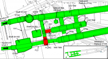
The station comprises two ticket halls; two escalator/concourse tunnels; two platform tunnels approximately 300m long each enlarged from the TBM tunnels; numerous cross passages; escape and ventilation tunnels (see Figure 1). All station tunnels will be constructed using sprayed concrete lining (SCL) techniques.
The geological conditions were the principal challenge for the design and construction of the tunnels. Excavation mainly took place within the Lambeth Group; the majority of SCL tunnels in London are excavated in London Clay. Crossrail awarded the contract for the construction of the Farringdon Crossrail station to a joint venture of Bam Nuttall, Ferrovial Agroman and Kier (BFK) in 2011.
Figure 1. Plan view of the West part of Farringdon station showing the location of the two temporary SCL structures (shown in red). The areas in green show the structures completed by September 2014
Dr. Sauer & Partners Limited Services
BFK appointed Dr. Sauer & Partners Limited as specialist consultant responsible for all sprayed concrete lining (SCL) tunnelling works prior to ring closure. Additional temporary sprayed concrete lining (SCL) structures were designed by Dr. Sauer & Partners Limited allowing for significant optimisation of the construction programme. These structures consist of a wraparound (PL2RC) and a temporary connection adit (CP1-CH1).
PL2RC, approximately 9.0m high by 8.0m wide, was aligned to intercept the future TBM drive and sized to envelop the segments, allowing a rapid connection between the SCL works and the TBM tunnel (see Figure 2). The final design utilised a 350mm thick sprayed fibre reinforced concrete primary lining. Steel bars or additional thickened zones around breakouts. This provided an efficient and buildable solution that satisfied both the tight construction programme and the contractor’s rigorous health and safety requirements.
A temporary SCL connection adit (CP1-CH1), approximately 7.0m high by 6.0m wide, was designed and constructed between a cross passage (CP1) and a concourse tunnel (CH1). These were successfully designed, checked and constructed within short timescales and allowed the SCL works to progress independently from the construction of the Western Ticket Hall and escalator barrel. Substantial cost, time and logistics benefits were realised for both the SCL and ticket hall box construction works.
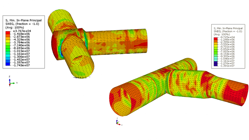
Non-linear finite element analyses (FEA) were carried out to support the design of the SCL structures. The capacity of the SCL and interaction with various other structures was assessed. Several load cases were tested and excavation steps simulated (see Figure 3). The FEA modelling benefitted from being able to use data from the project team's "live" 3D geological model. This model was updated in real time, with data obtained from ground investigation works and tunnel excavation. Designers were thus given the best possible estimate of anticipated geology.

Figure 2. CP1 (left), CP1-CH1 connection adit (centre) and PL2RC (right)

Figure 3. FE models showing compressive stresses at the intrados of PL2RC (top left) and CP1-CH1 (bottom right) primary lining.
