You are here
Featured Projects - Channel Tunnel Rail Link
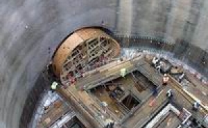
The Corsica Street Ventilation Shaft comprise the permanent pressure relief and ventilation adit connecting the down line running tunnel to the shaft and the temporary access adit tunnel, which will be used to inspect the TBM cutter head and shield before being used to construct the permanent emergency access opening to the down line running tunnel.
The ventilation adit was designed as a permanent sprayed concrete lined tunnel constructed in two phases, primary and secondary linings. The required watertightness was achieved by staggering the joint locations between the primary and secondary linings, utilising internal curing agents and steel fibres in the secondary lining sprayed concrete and using injectable flexible tubes in the joints of the secondary lining.
At present the ventilation adit design comprises a 6.9 m span by 6.725 m high tunnel, 5.869 m length from the shaft along the top of the up line running tunnel. The tunnel then turns around a 90º bend, 9.464 m on centre, followed by a further 0.5 m straight before a 3 m long linear transition to the enlarged ventilation adit to give the required space to safely construct the drop shaft. The enlarged ventilation adit comprises a 10 m span by 8.225 m high tunnel 13.56 m in length and terminates in a domed headwall.
The reinforced sprayed concrete drop shaft comprises a hexagonal internal shape with a curved sided rectangular excavation. Initially the shaft will be constructed short of the TBM cutter head envelope until the TBM has passed. Universal steel beams (USB) will be installed along the tunnel axis and encased in concrete. After, the TBM has passed internal propping will be installed in the running tunnel prior to removal of segments (roof only), the remaining bottom half of the ring will be supported by steel angles bolted into the USB. Once two rings have been supported the steel angles will be concreted in with reinforced concrete. Once the concrete has gained sufficient strength the remaining two rings can be completed in a similar operation. Finally, the two drop shaft walls perpendicular to the tunnel can be extended to the segments concreted in with appropriate waterproofing measures.
The drop shaft at the junction with the enlarged ventilation tunnel will be designed and reinforced to transfer the hoop loads in the tunnel lining around the opening. The shaft walls will be designed to support the long-term lateral earth and water pressures along with the vertical loads transferred from the enlarged ventilation and running tunnels. The remaining PCC tunnel segments will be checked for the loads due to the overlying reinforced concrete drop shaft.
The temporary access tunnel to be used for the TBM cutter head and shield inspection will be constructed using a non-permanent primary sprayed concrete lining designed to support the short-term ground loads. Short-term dewatering of the groundwater bearing Harwich formation will be initially carried out from the shaft during excavation and then continued using pipes installed through the lining once the tunnel has been constructed.
The preliminary opening design has been based on minimising the opening size due to the high hoop loads in the lower parts of the shaft lining. However, this creates some disadvantages when constructing the high access tunnel, 10.518 m high by 7.782 m span, required for the inspection chamber. To improve the construction of the chamber a temporary opening might be constructed with a horizontal strut across the opening to reduce the second forces in the ring beam.
In order to stiffen the high chamber sufficiently to be stable during the TBM break-through, the spaces around the TBM cutter head including a 500 mm gap will be in-filled with mass concrete. The remaining space after the TBM passes the chamber will be filled by reinforced concrete, creating the tunnel ring with integral 2.65 m wide by 3 m high opening into the shaft. Some minor adjustments will be required to cope with the actual locations of the tunnel lateral ring joints.

