You are here
Design of Tunnel Linings using Capacity Limit Curves
Design of Tunnel Linings using Capacity Limit Curves
Proceedings of the 8th International Conference on Computer Methods and Advances in Geomechanics, May 22-28, 1994
ABSTRACT
The structural layout of the tunnel concrete linings is dictated by various factors; geology and hydrological conditions, overburden depth, size and shape of the tunnel and the method of excavation and support to name the most influential ones. Varying tunnel lining thicknesses and loading conditions imposed by the above factors require multiple computation cross sections to represent typical and critical conditions relevant for the structural designs. The computations, typically carried out by the numerical techniques i.e. finite element and difference methods, embedded frames, etc. produce a vast number of section forces for which the linings have to be designed. For an effective evaluation of lining forces the principle of capacity limit curves, based on the German Norm DIN 1045 for an economical design of plain and reinforced concrete linings, has been automated. The program shows both numerically and graphically the capacity of either reinforced or unreinforced tunnel concrete lining.
INTRODUCTION
The number and sophistication of design computations carried out for structural linings of transportation tunnels have been steadily increasing during the past several years. The client's and designer's need to provide a satisfactory estimate of expected deformations, loading of the lining shell, impact of the tunnel construction on neigh boroughing surface and subsurface structures and associated legal concerns, as well as the safety of the tunnel structure itself are to be seen as the driving forces of this development. The vehicle, however, which has enabled this progress has been the steadily improving capability and computation power of both software and hardware which are being used to as realistically as possible simulate the stress redistributions caused by the excavation and support process underground.
Although the design of tunnel concrete linings is primarily dictated by structural requirements, constructability and practicability issues also influence the layout of the cross section. Depending on the computed section forces as well as the overall design concept of the tunnel, the linings can be carried out as a reinforced or an unreinforced cross section.
The paper introduces the basic considerations of the Capacity Limit Curves (CLC) and demonstrates the design of cross sections or concrete lined tunnels by the use of CLC's. Such curves determine all combinations of bending moment and thrust that can be endured by a given concrete or shotcrete cross section. For the calculation of an asymmetrically reinforced cross section, a method is used to minimize the percentage of reinforcement for an optional number of given section forces.
The concept of capacity limit curves has been use for various tunnel designs including the Washington, D. C. Metro, the Lehigh Highway Tunnel No. 2, PA and the light rail starter tunnels in Dallas, TX among others. An example toward the end of the discussion illustrates the tunnel lining design procedure.
List of Symbols
Geometry
b = width of cross section
d = height of cross section
hd = height of concrete in compression
y = distance from point of load compression to a point in zone of compression
a = distance or point of maximum compression to point of resultant thrust
d1,d2 = concrete cover
AS1,AS2 = total area or reinforcement
Strains
eb = concrete strain
ebl = maximum concrete strain
es = steel strain
eS2 = maximum steel strain
ef = limiting steel strain at yield
Stresses and Design Values
bR = concrete strength
bS = steel strength
sb = concrete stress
sS1sS2 = steel stress
Section Forces
Db = resultant thrust
N,NU = thrust and ultimate thrust
M,MU = bending moment and ultimate bending moment
2. PRINCIPLES OF CAPACITY LIMIT CURVES
2.1 Design Codes
The concept of capacity limit curves is based on the German Building Code DIN 1045 (Sauer, et. al., 1990). Historically, frequent use of the New Austrian Tunnelling Method (NATM) which uses a cast-in -place unreinforced inner concrete lining as line tunnels and a rather thin flexible shotcrete lining as initial support (Sauer, 1986) has appealed to many owners of subway, highway and highspeed rail tunnels in Germany and Europe due to its economic advantage. Extensive research and experience associated with this method resulted in the definition of a new German Code for plain structural concrete which was implemented into the Building Code DIN 1045 in 1984 (Gnilsen, 1986).
In contrast to ACI 318.1 (Building Code Requirements for Structural Plain Concrete) which uses the factored loads of section 9.2 of 318 but limits the stresses thereof to 'permissible stresses', the DIN 1045 is based for both unreinforced as well as reinforced concrete on the ultimate strength design method similar to ACI 318 (Building Code Requirements for Reinforced Concrete). The DIN 1045 allows for limited cracking of the unreinforced concrete section within stability and safety requirements. This results in thinner, more economical lining designs. Therefore the capacity limit curves have been developed based on the German Building Code. The concept itself can be applied using the ACI norm or any other building concrete code. However, using concrete codes for the structural design of tunnel linings, considerations shall be given to assumptions made in the codes and their intended area of use as most of the codes have been written for above ground structures ?(O'Rourke, 1984). Design codes for above ground structures typically lack the contributing support function of the ground and the affect of the excavation method which are both of importance to lining capacity and therefore cost (Einstein, et. al., 1980 and Cording, et. al., 1976).
|
According to the design principles of the DIN 1045, the section forces due to working load are multiplied by the safety factors and are compared with section forces at ultimate strength for the given cross section taking into account the material characteristics of concrete and reinforcing steel and the associated strain. This is achieved either by using design diagrams or by the use of commercially available software packages. In a typical design exercise where a uniform reinforcement is to be used, a verification of sufficient capacity is required at several locations. The principle of capacity limit curves is to present computed thrust (N) and bending moment (M) combinations versus all possible of maximum allowable section forces in a diagram. For this purpose all combinations of calculated section forces for a given plain or reinforced cross section are graphed in a diagram with the thrust at the abscissa and the bending moment at the ordinate. Similarly, all possible ultimate section forces, derived from the state of strain at ultimate strength and divided by the safety factors (SF), are graphed in the diagram forming a continuous curve, the actual capacity limit curve (CLC) which encloses a range of allowable combinations M and N. Those section force combinations outside this curve cannot be endured by the given cross section with a satisfactory safety factor. The derivation of capacity limit curves was automated using a computer program which accomplishes this task for plain as well as reinforced concrete in numerical and graphical output format (Bauer, 1989). The graphical presentation (Figure 1) shows the capacity limit curve for a given unreinforced (CLC) and reinforced (CLC) concrete lining and allows for an easy verification of the load bearing capacity of a given cross section along an entire tunnel section in a single diagram. Moreover, remaining bearing reserves can be promptly evaluated. This becomes especially important when encountering geologic conditions during tunnelling drivage which deviate from load assumptions used in the design. By plotting the section forces derived from actually encountered loads in the already existing diagram, the sufficiency or insufficiency of the tunnel cross section regarding bearing capacity and safety factor can be checked without the need of any further calculations. |
Figure 1. Capacity Limit Curves for unreinforced and reinforced concrete cross section. |
3. DERIVIATION OF CAPACITY LIMIT CURVES
|
The deriviation of CLC's is based on the DIN 1045. Further assumptions of the DIN 1045 can be found in Leohardt, et. al., 1973. 3.1. Section Forces at Ultimate Strength Using the definitions in Figure 2:
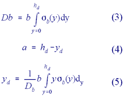
If the entire concrete section is in compression, Eq. (1) is replaced by: hd = d (2) For a constant width of the concrete cross section, the resultant thrust acting in the concrete can be computed according to Eq. (3). The distance between the outer fibre of the concrete in compression and the eccentric resultant thrust is given in Eq. (4): |
Figure 2. Definitions of section forces and state of strain at Ultimate Strength for a regular cross section. |
|
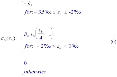
The dependence of sb (y) on the strain eb (y) is determined by the material behaviour of concrete. Figure 3a shows the stress-strain relationship defined as: |
Figure 3.Limiting stress-strain diagrams for concrete (3a) and steel (3b) according to DIN 1045. |

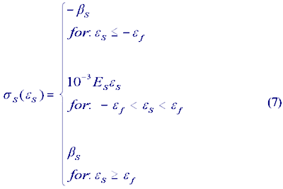
Equations (3) and (5) can be solved analytically regarding Eqn. (1), (2), and (6). As the state of strain for the steel is known by assuming full bonding between the reinforceingsteel members and the concrete, the state of stress in the steel can be derived using the stress-strain relationship as shown in Figure 3b:

Using Eqn. (3), (4), (7) the section forces at ultimate strength can be derived using equilibrium conditions. From SN=0:
NU = AS1sS1 + AS2sS2 + Db (8)
and from SM = 0 with respect to the neutral axis of the concrete cross section:
MU = -Db(d/2-a)-AS1 sS1(d/2-d1) + AS2 sS2(d/2-d2) (9)
3.2. Maximum Allowable Section Forces
3.2.l Capacity Limit Curves (CLCr) for Reinforced Concrete
Using all possible combinations of section forces at ultimate strength for reinforced concrete as computed in 3.1 and dividing by the appropriate safety factors, yields the coordinates of the capacity limit curve expressed in the max. allowable bending moment (ordinate) which are given as:

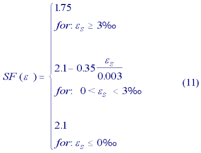
The DIN 1045 distinguishes safety factors to reflect whether failure of the cross section occurs with advance warning (SF = 1.75) or without (SF = 2.1) as indicated by the state of strain and the development of cracks in the concrete. Therefore safety factors are given as stated in Eq. (11):

3.2.2 Capacity Limit Curves (CLC.)for Underground
The structural design for plain concrete according to the Din 1045 is based on the ultimate strength design as outlined in 3.1. The derivation of the capacity limit curves is according to sections 3.1 and 3.2.1 setting the reinforced steel areas equal to zero (AS1=AS2=0). The safety factor for plain concrete is constant, being 2.1, and therefore independent of the state of strain in the cross section. The concrete section in tension cannot be incorporated in the design and the crack may reach to the neutral axis. An approximation (Grasser, 1985) for the eccentricity of the resultant thrust is given as:
e/d < 0.3 (12)
4. STRUCTURAL DESIGN
4.1 General
In contrast to concrete designs for regular building construction where the reinforcement of concrete is adjusted segmentally along the length of a structural member according to the computed section forces, it is common practice in tunnel designs to base the reinforcement on the most favourable loading condition and use constant reinforcement along the perimeter and constant length of equal lining thickness. This is mainly due to constructibility reasons.
The computational approach to arrive at the equired reinforcement as applied by the developed computer program is introduced below.
4.2 Reinforcement Optimization Using CLC's
Essential parameters involved in the optimization process are the strength of the concrete and steel, the thickness of the concrete lining and the amount of reinforcement. Some combinations of these parameters are limited by the building code or often dictated by the design. The variation of the remaining free parameters and their evaluation can be easily controlled by a computer program.
An illustration of the optimization principles can be shown using a simplified example where lining thickness and concrete design strength are assumed to be constant. The first task is to determine whether the given bending moment and thrust combinations are bound by the CLC of plain concrete. If reinforcement is necessary, then the required one-or-two- sided reinforcement has to be calculated. In order to take full advantage of the optimization process, at least one pair of the given section forces should lie on the CLC. This state is found by an interactive procedure which consists of varying the reinforcing steel area until the difference between the given section forces and allowable section force including the reinforcing steel becomes zero for any component. For double layered reinforcement the minimum of the reinforcement sum is introduced as a criterion for the optimization process. Herein the symmetrical reinforcement leads to an upper limit. It is then efficient to continue the tracing process from this symmetrical optimum to reach the reinforcement amounts of the unsymmetrically reinforced section. For this purpose the difference in reinforcing steel areas is varied until the sum becomes a minimum.
|
5. TUNNEL LINING DESIGN A typical tunnel lining design is illustrated on the design project for the light rail system starter tunnels DART Section NC- 1B for the Dallas Area Rapid Transit in Dallas, TX (see Allen and Keahey,1993). The main project components include two roughly 17,000 foot long single track tunnels with a diameter of about 21 feet, miscellaneous ventilation structures and one deep underground station, the City Place Station. While the station is located entirely in unweathered rock conditions, the location of the tunnels ranges from soft ground to rock conditions with the main tunnel portions driven through the rather favourable unweathered Austin Chalk. In order to enhance a competitive bidding process aiming at a lower bid prices for tunnel construction, DART offered two tunnel design alternatives to the bidders: one 'conventional tunnel design, a circular section designed for the use of tunnel boring machines and a NATM design. Similarly to the NATM, the conventional alternative uses shotcrete as the initial tunnel support followed by a cast-in-place concrete lining installed where the tunnels are driven through soft ground and mixed face ground conditions. To adjust to ground conditions, four basic ground support categories with varying initial support measures were defined in both alternatives. |
Figure 4. Finite Element mesh and geological conditions for the DART Project. |
The Dr. G. Sauer Corp. carried out the structural design computations for the underground openings using the finite element method in connection with the capacity limit curve concept. For the two tunnel alternatives alone, a total of ten computation cross sections were established to account for the different ground support categories as well as site specifics including adjacent underground storm sewers, narrow pillar configurations between the tubes, piles supporting the roadway bridges above, to name the most common. The computations were carried out using the finite element program ABAQUS, Ver.4.8., a general purpose program designed to serve advanced structural needs.
It features material behaviour models required in soil and rock excavations, e.g. an extended Drucker-Prager failure criterion. To represent the ground, eight-noded plain strain elements where elements were utilized; the concrete and shotcrete lining elements were represented by three-noded curved beam elements. The finite element mesh used for one of the computation cross sections is illustrated in Figure 4.
To achieve sufficient accuracy on stress distribution and lining behaviour in these mixed face conditions a fine mesh grading was selected resulting in a total of 18 beam elements for the shotcrete, and another 18 elements for the shotcrete lining. The program provides output at two integration points for each element resulting in 36 thrustmoment combinations for each, shotcrete and concrete.
The resulting thrust and moment diagrams for the shotcrete lining after excavation of top heading, bench and invert, are displayed in Figures 5a and 5b respectively.
|
In soft ground conditions the initial shotcrete lining is reinforced with lattice girders which are set at each excavation around spacings of approximately 1 meter and welded wire fabric at both inside and ground side. The design task consists of verifying the capacity of the reinforced cross section. The reinforcing amount of the lattice girder bars is taken into account along with the welded wire fabric. The capacity limit curve diagram in Figure 6 displays that the 20cm thick reinforced shotcrete section bears capacity reserves. Due to possible aggressive ground waters the final lining computations assume the complete deterioration of the initial shotcrete lining. Figure 7 shows that the unreinforced 25 cm thick cast-in-place concrete lining also bears capacity reserves. 6. SUMMARY AND CONCLUSION The design of reinforced tunnel concrete linings is expeditiously performed using capacity limit curves. The computer program presented allows for the optimization of structurally required reinforcement or verification of selected reinforcement. Graphically and numerically the bearing capacity of a given cross section under given loading conditions can be verified. Here, the program has been developed on the basis of the German Building Code 1045, however, the conceptual approach can be applied similarly to the ACI code or any other relevant concrete code. Acknowledgements The authors would like to thank Mr. Eduardo Ugarte design manager for DART for his review and DART's permission to publish the project data contained in this paper. References Allen, A. A. Keahey W. K. DART's ASAP EIS, Civil Engineering Magazine, August 1993, Vol. 63, No. 8. American Concrete Institute, Committee 318-92, Building Code Requirements for Reinforced Concrete. American Concrete Institute, Committee 318.1-92, Building Code Requirements for Structural Plain Concrete and Commentary. Bauer, E., 1939 Beschreibung zum Rechenprogramm BETON (Manual for the software package BETON), EDV-Beratung und Entwicklung, Graz, Austria. Cording, E. J. Mathews, A. A., Peck, R. B., 1976. Design Criteria for Permanent Structural Linings for Station Excavations in Rock, Washington Metropolitan Area Transit Authority. Din 1045, 1988. Concrete Design and Construction, Deutsches Institut fur Normungen E.V., Beuth Verlag Gmbh., Berlin,(FRG). Einstein, H.H., C.W., 1980 Improved Design of Tunnel Supports, Report No. UMTA-MA-06-0100-80-4, U.S. Department of Transportation. Gnilsen, R., 1986. Unreinforced Concrete Tunnel Lining - Design Concepts, Technical Bulletin Vol. 1. Grasser E., 1985 Bemessung fur Biegung mit L䮧skraft, Schub und Torsion (Lectures on Concrete Design), Springer Verlag, 2nd Edition. O'Rourke, T. D., (Editor), 1984. Guidelines for Tunnel Lining Design, Prepared by the Technical Committe on Tunnel Lining Design of the Underground Technology Research Council, American Society of Civil Engineers, New York,N.Y. Sauer, G., 1986 Theorie und Praxis der Not (NATM Theory and Practice Tunnel (STUVA) p.280 ff., Cologne, FRG. Sauer, G., Dietmaier, P., Bauer, E., 1990 Bemessung von Tunnelschalen fur Biegung und Normalkraft mittels Tragsicherheitskurven (Design of Tunnel concrete Lining using Capacity Limit Curves), Der Bauingenieur, Springer Verlag. |
Figure 5. The initial shotcrete thrust diagram (5a) and moment diagram (5b).
Figure 6. Capacity limit curve for reinforced shotcrete lining.
Figure 7. Capacity limit curve for unreinforced shotcrete lining. |


