You are here
NATM Ground Support Concepts and their effect on Contract Practices
Rapid Excavation and Tunneling Conference, June 11-14, 1989
ABSTRACT
The main advantage of the New Austrian Tunneling Method over conventional drill and blast techniques, TBMs and shields is its outstanding flexibility. Many different support concepts help to cope with all but the most adverse conditions. A considerable variety of unique additional support measurements provide a functional tool when dealing with particularly difficult conditions or restricting requirements. The resulting adaptability of NATM with respect to geometric and geologic changes is a cornerstone to providing an economic design and to a safe and unhindered execution of the tunnel work.
To take best advantage of this flexibility and to emphasize its cost-saving capacity, NATM explicitly extends the design period into the construction phase. In accordance with corresponding ground classes or other anticipated conditions, a number of basic support categories and an array of additional support measurements are established during the actual design phase. The decision for applying a particular support category at a specific location and for necessary additions to the given support scheme, however, is regularly made on site after each advance, and is determined by the key persons involved in the construction.
Contract documents must reflect this approach to facilitate the execution of the work and to curtail construction costs. Biased distributions of risks, however, can adversely effect the envisioned benefits. Consequently, the respective responsibilities of engineer, contractor, and client need to be redefined.
A METHOD WITH MANY NAMES
It may sometimes happen to famous and successful offspring that more than one father is claiming paternity and tries to impose his name, but to successful ideas it almost certainly always does, and perhaps the number of prospective candidates can be seen as an indicator of the potential of whatever the new finding or development was.
In the case of the technique that most people refer to as the New Austrian Tunneling Method, it has frequently been argued that it contained nothing particularly 'new' nor particularly 'Austrian,' and the only thing commonly accepted is that it somehow relates to creating underground space. The many tags that have been attached to it during the past twenty plus years, however - mainly more descriptive and less compromising designations such as "Shotcrete Methods", "Sequential Support Method," or "Observational Tunneling method" - reveal that there is more innovative spirit behind it than some experts would like to concede. So far, and for the purpose of this paper, we may continue using the acronym NATM without being mistaken.
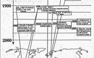
Looking into the background of some of the constituents that make up this peculiar method, one naturally senses the excitement of being put in front of a historic atlas (Figure 2):
- 1848, Prague, first attempt of using fast-setting mortar as initial tunnel support ;
- 1872, Zurich, Karl Ritter proposes to apply curved tunnel sections in squeezing ground;
- 1872, Berlin, F. Rziha's conception of a tunnel support that would avoid rock loads rather than to oppose it;
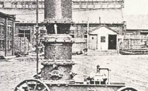
- 1908, Chicago, Carl E. Akeley, taxidermist by trade, invents a mortar spraying machine (Figure 2);
- 1911, Allentown, first approved patent for a 'cementgun' that shoots 'gunite' onto slopes;
- 1914, Denver, application of gunite in coal mines for fire protection; and since the early
- 1920's, USA, use of gunite in tunnel construction as a protective layer2,4.
So, what's really 'new' or 'Austrian' with this method?
For one, there was L. v. Rabcewicz who created, in 1948, a concept of controlled rock deformation, an idea not entirely new perhaps, but for sure he was Austrian. His concept, though, of a dual-lining system involving systematic anchoring as a primary or initial tunnel support and cast-in-place concrete as a final, secondary lining, together with his idea of utilizing controlled deformation as a means of reducing rock loads were indisputably innovative. Was he, then, the father of NATM?
Perhaps not, because somewhere the mysterious mortarspraying machine was left behind. Almost forgotten by tunnelers, improved revolver shotcreting machines did a good job for slope stabilization, as for example at the Runserau Hydroelectric Power Project, Austria, where, in 1954, one of the diversion tunnels ran into difficult ground.
Anton Brunner, superintendent for the tunneling operations at the plant, became annoyed of stabilizing the squeezing ground with the usual amount of steel and timber that inevitably hampered any further progress at the excavation face. He retained one of these 'new' machines and applied, for the first time, shotcrete as a supporting element onto the tunnel perimeter immediately after he had opened an area of excavations.
Since this was without precedence and the consulting authorities did not have much faith in his approach, he must assume full responsibility for the safety of workmen and equipment - but it did work, indeed! In 1958 then, he filed for a patent for his concept of tunnel construction in squeezing ground that he called "Shotcrete Method."
Was he the father of NATM then, Brunner? Not really.There is still another element inherent in what some so persistently call the 'New Austrian Tunneling Method': in-situ-measurements. Although monitoring was nothing new at tunnel construction sites either, Mueller another Austrian, realized that careful observation of deformations and
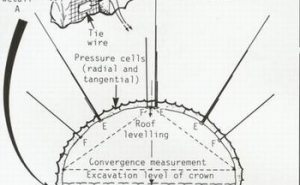
loads occurring at the tunnel perimeter was a necessity to effectively circumvent excessive rock loads. Hence, in 1960, he and others developed a system for measuring the time-dependent deformation around the tunnel opening that would allow a meaningful interpretation of the collected data on the basis of the rock mechanics theory that was previously developed by the Salzburger Kreis of tunneling experts (Figure 3).
Shotcrete lining and systematic rockbolting represented an almost ideal all-purpose initial tunnel support. Together with an array of measurements within the tunnel, this exceptionally adaptable and smooth but appropriately resistant lining was capable of accomplishing what so many had envisioned - minimizing rock load by accepting necessary deformation.
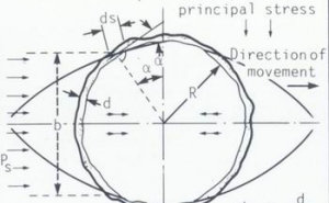
But yet, to constitute a modern tunneling concept a reliable numerical method for designing the appropriate tunnel lining was needed. It began with rather conventional attempts such as the 'shear failure theory' of Rabcewicz, Sattler and Gobiet" (Figure 4). Starting in downtown Frankfurt in 1969, the application of NATM for tunnels in soft ground finally led to a series of detailed scientific investigations involving detailed model tests, structural calculations and monitoring programs on various tunnel projects' . Finally, with the introduction of finite element method calculations, reliable projections of settlements and lining stresses could be generated as a basis for developing standard structural analyses.
Many other projects followed. As experience grew, refinements, enhancements, and diversification of NATM spread all over the field of underground construction and - we believe it is fair to say - all over the world.
UNSUREPASSED FLEXIBILITY
Before going into the details of the various ground support concepts for NATM, we should quickly review some basic considerations that are postulated with this method.
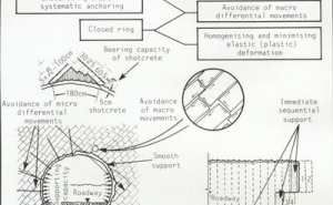
As we have seen before, the conception of how ground performs during tunnel excavation has gone a long way before one has established the theory of a timedependent structural behavior. According to this new understanding it was apparent that, by permitting controlled deformation, no massive and rigid tunnel support was called for to withstand excessive ground loads but rather thin and supple linings. The emerging insight, especially that the ground surrounding a cavity is ordinarily well capable of assuming the additional loads triggered by the excavation, led to important conclusions (Figure 5):
(1) The initial tunnel lining should primarily support the immediate layers of the ground surrounding the opening (the loosening zone), and guard them against proceeding deterioration. (2) The faster the initial support is in place and functional, the smaller the loosening zone; the initial lining should, however, not attract additional forces by being tougher than necessary. (3) Since the 'load carrying arch' that develops around the opening will be of more or less circular shape, the size of the loosening zone and the burden imposed on the lining can be minimized by adopting this shape for the opening as well; at least, abrupt changes along the tunnel perimeter must be avoided. (4) The smaller the loosening zone and the unsupported area of the tunnel, the smaller the loads and the actual amount of deformation and surface settlement.
We must not forget, however, that the basis of this knowledge was the perception of a time-dependent behavior of all grounds, from the most competent rock down to cohesionless soils. For this reason, an economic design must require that certain excavation steps are performed in a specific sequence and at a specified time frame. Since the time needed to excavate a specific volume of rock or soil is directly dependent on that volume, the largest excavation volume per advance that can be handled within a given time becomes a determining factor. This, in turn, circumscribes the greatest possible cross sectional area for one heading as well as the related appropriate length of advance. Once a practicable cross section is defined, the length of advance is the remaining variable that easily allows to adapt to changing conditions without altering the excavation area.
With this method, on the other hand, neither geometric nor geologic changes of tunneling conditions do normally cause any problems. Obviously, there is hardly another construction method that has to do with materials that are better suited for being modeled into different shapes: a cavity in rock or soil, and a shotcrete lining. No prefabricated elements are required, no forms needed. And, if worse comes to worst, shotcrete, the main supporting element, is always readily at hand, in exactly the amount and thickness required here and now.
Of course, while designing the initial tunnel support one will always try to facilitate a certain routine of the tunneling operations by avoiding major changes of the excavation sequences. Therefore, the primary tools for adjusting to changing geologic conditions are the variation of length of advance, the lining thickness, and whatever as additional support measurements is applicable.
Equipped with all this historical and theoretical background we may attempt an hypothetical application: assuming a medium-size tunnel cross section, e.g. 100 square yards, what would the general characteristics of some basic NATM concepts be?
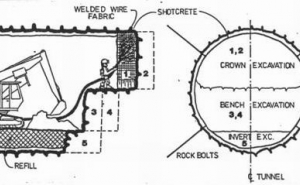
We might start with the most simple conditions: more or less competent rock with standup times of several days and more. Here, the usual and probably most economic way would be to subdivide the excavation area into top heading and bench. The top heading can advance without major restrictions, and will finally be followed by a simple bench excavation. With increasing diameter of the tunnel, the entire cross section can further be subdivided to suit the excavation equipment employed. For smaller cross sections, full face excavation may economically be applied, provided that the largest permissible area will not be exceeded.
The advantages of this scheme are obvious: the hole variety of conventional and inexpensive tunneling equipment can be used. The unrestricted advance of the top heading with regard to the distance to the bench allows to expediently organize and spread tunneling operations over the entire construction area.
But this concept has its limitations where less reliable ground conditions come into play. In highly stressed or weathered rock and especially in soft ground, advanced top headings often generate irregular and high convergencies on account of inducing shear planes in the sidewall. The only remedy to that lies in heavy abutments or numbers of additional rockbolts for the top heading that result in an oversized initial lining, in which case the additional costs offset the possible advantages.
Because of the higher settlements, the concept of an advanced top heading is only occasionally applied in urban tunneling. Here, as well as wherever squeezing rock conditions or very loose material is encountered with standup times of only one to several hours, a sequential full face excavation represents a much more competent approach.
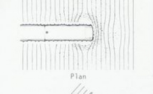
Looking back into theory for a moment, we assume that a wave-like distribution of stresses encircles the heading. Verified by in-situmeasurements, this pressure wave can also be observed by the abrupt displacement processes which sometimes take place in certain sections of the tunnel and in the surrounding ground. This phenomenon also creates stress-reduced protective zones and is difficult to understand in terms of continuum mechanic but can quite plausibly be explained with a time-dependent structural behavior30 that relates to the size of the tunnel opening (Figure 6).
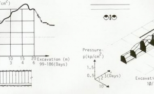
According to model tests and many in-situ-measurements, periodic stress peaks surround the tunnel heading like waves in a pond caused by the plunge of a stone. These three-dimensional stress waves accompany the drivage operations at linear intervals. The results of the investigations suggest the following characteristic stress distribution pattern in the vicinity of the tunnel (Figure 7):
(1) the pressure increases relatively rapidly about 1 to 1.5 tunnel diameters [Dt] in front of the heading, with its peak only about 0.5 Dt away from the excavation face;
(2) the second maximum follows about 1.5 to 2 Dt behind the face, provided that there is adequate support;
(3) the geometric center of the wave-like occurrence of stress peaks lies about 0.5 Dt behind the face - and that is exactly where we can expect the absolute stress minimum during the tunneling operations.
It is important to realize that there is a zone between the two stress maxima that contains and protects the excavation area. This is the place where initial tunnel support must be installed and completed, and where the shotcrete must be sufficiently hardened. The absolute stress maximum follows close by, and if the support is not adequate, deformations of bolting plates, cracks in the initial lining, etc. may develop in an area about 1.5 to 2 Dt away from the face.
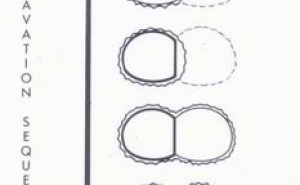
With respect to our imaginary support concept, all this means that we must find a way to accomplish two major tasks: for one, we must subdivide our excavation area into portions small enough to allow complete installation of the respective part of initial lining within the term of the relatively short standup time. On the other hand, we must ascertain that the initial lining forms a complete ringlike structure within the protective zone, which means within approximately one tunnel diameter of distance to the foremost heading.
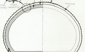
Small and uniform convergencies, minimum loosening zones and minimum settlements resulting in low costs for initial tunnel support are the striking advantages of a typical NATM support concept that can accomplish these requirements (Figure 11). A well organized working crew can maintain a relatively good advance rate with a minimum of equipment and manpower required. Additional support means placed in advance, such as grouted or ungrouted spiling, can further increase standup times and reduce settlements. All in all, this concept provides not only a safe solution for mining through fault zones or talus but also represents a very promising and economic approach for urban tunneling in soft ground.
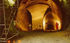
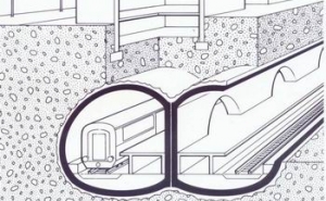
Of course, there are limits to that concept, and other configurations such as multiple drifts must be considered when things get worse. For example, a subdivided top heading with temporary invert may be applied, as well as one or more sidewall drifts (Figure 8). These drifts render the advantage of representing small independent structural support systems all by themselves. That way, the created stresses as well as the excavation volume per heading become smaller and more controllable. While the respective drifts can proceed without major restrictions, the remaining tunnel area must be excavated according to the principles pointed out for the full-face excavation, which means closure of the initial support structure within 1 Dt. A certain pre-draining, the advantages of a full scale site exploration, and the effective longitudinal support created by the drifts are to be mentioned in favor of this concept.
Clearly enough, however, there are quite a few disadvantages. The largely reduced working space becomes a major hinderance to the advance rate. Extremely small excavation equipment is sometimes necessary to fit into the drifts. And last but not least, some portions of the initial linings of these drifts must be removed during the main heading and serve only temporary purposes. But still, this concept represents a viable option for tunneling under extreme geologic conditions.
At the upper range of practicable solutions to tunneling problems in conjunction with NATM we will find compaction grouting, ground freezing, and compressed air tunneling. Also the use of the so called "Barrel Vault Method" or of jet grouting will fall into the category of reliable options for tunneling under special conditions such as for underpasses under highways, railways, airport runways, buildings or rivers, and tunneling in groundwater. While horizontal jet grouting and ground freezing require the involvement of highly specialized subcontractors, the use of compressed air in connection with NATM is rather uncomplicated and the approach was quite frequently and successfully employed on recent subway projects in Europe as a means of groundwater control.
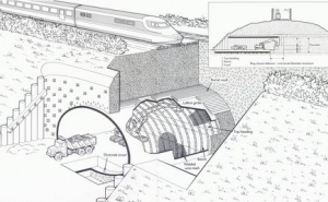
Likewise, the Barrel Vault Method has now more frequently come to be used in Europe to ensure safe mining operations under railway embankments and expressways and wherever settlements must be kept at the observational limit (Figure 9). This method consists of horizontally placing metal grouting pipes along the tunnel perimeter above the upper part of the crown and ahead of the tunnel heading. After the high-pressure grouting is completed, the cylindrical mass of cement grout, reinforced with the steel pipes, creates a kind of horizontal piles, arranged in a way that resembles the form of a barrel. This outer shell longitudinally bridges the unsupported area between the undisturbed ground in front of the excavation area and the completed initial tunnel lining behind it. Again, this measurement is designed to increase the standup time and prevent raveling.
Difficult geologic conditions present just one of many possible problems that tunnel designers very often have to face. Shallow cover and demanding environmental circumstances contribute to another, and since both tend to occur in conjunction with one another in urban tunneling, the construction of subways or highway tunnels through downtown areas creates some lasting headache to not only designers, but to abutters and owners alike. In an apparent lack of economic solutions for a mined tunnel, large open cuts too often bisect entire business districts like an artificial river and paralyze the neighborhood for years. Traffic patterns get completely out of control, and dust, noise, vibration and air pollution ruin the everyday routine of an entire neighborhood.
There are, however, construction concepts available that can bring a significant relief by putting all major construction activities under ground and prevent the hole area from being torn into the separate pieces. One of this concepts consists of a combination of NATM with an abbreviated version of the usual cut-and-cover construction.
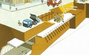
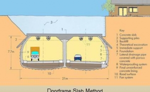
The concept of this so called Door Frame Slab Method (Figure 10) is to start off with a shallow open cut of rather limited length and to place a reinforced concrete slab at the elevation of the later roof of the tunnel. Small bore piles with a spacing of several feet are then installed at both edges of the slab with some outward inclination, that may in cases be complemented by another row of piles along the centerline of the tunnel. Once these piles are put in place, the cut can be backfilled and the surface restored. Most utilities can be temporarily underpinned and left in the original location while the small open cut proceeds along the alignment of the projected tunnel quickly and without causing much of a disturbance to the area.
Now, under the umbrella of concrete slab and bore piles sheltering the tunnel crown, a regular NATM excavation procedure can take place, probably with top heading and bench as outlined before. In the crown portion of the tunnel, the shotcrete lining connects into the concrete slab which becomes part of the initial lining. Resting on the undisturbed ground on one side and the finished shotcrete shell on the other, however, the concrete slab primarily serves as a means of improving the ground by longitudinally spanning the unsupported area of the current advance.
Very limited settlements and safe tunneling operations make this approach technically attractive, while its environmental advantages are also striking. The outlined method assures simple traffic control, diminished requirements for utility relocation, temporary deckings and cross-overs, reduced construction time due to a staggered construction sequence and unhindered mining operations, and less need for construction easements for temporary muck deposits and alike. Most of all, the bulk of the hauling and other construction operations takes place under ground, so that the environmental impact of the construction in terms of noise, dust and other air pollution is significantly less critical.
WHO IS TO BE BLAMED?
Naturally, things become much more complicated once we leave the firm ground of pure engineering considerations and proceed towards applying our concept in the real world of legal matters and what appears to be Nightmare No.1: responsibility and risks. Straight forward statements such as "We don't assume any!" can more frequently be heard than the rather serious question of "Who is taking what part of it?" Since there is hardly an undertaking on earth that would not involve risks and respective responsibilities - and tunneling is certainly one of the least predictable enterprises - this question deserves our undivided attention.
Consider taking a ride in one of New York City's famous Yellow Cabs to get from downtown Manhattan to one of the airports where we need to catch our plane in time. Visualizing the typical traffic conditions in the city on a weekday afternoon, let us explore the general rules our ride is based upon, and review the way we pay for our trip.
Allegorically, so as to compare this situation with a tunnel construction contract, we may contemplate the Highway Code as representing the General Provisions, and the local traffic regulations portraying the Special Provisions. The street map of the city and the local traffic control means (traffic signals, signs, pavement markings) would signify the Contract Drawings much in the way as the cabdriver and his cab would symbolize the Contractor and his on-site equipment. What's left is the Construction Inspection and the Authority, represented by traffic police and us, the paying passenger; and, most important, consider the uncertainties of the traffic through New York City's rush hour, very appropriately depicting the geologic conditions of the site.
To stress your imagination a little further, let's suppose that our cabdriver just arrived from, say, Miami, and that he is only vaguely familiar with the local street network and traffic conditions, and so were all other cabdrivers we could find in the city. So, all he really knows is the Highway Code and how to maneuver his car. In order to provide him with the additional information he needs to do his job, and for us to find the most economic and effective route to the airport, we - ourselves coming from some other place - have hired an assistant, the personified Consultant, to perform some in-depth studies and to prepare the Contract Documents, here in form of rout maps, local traffic information and the like.
With all the key players in place, we now should investigate in the various ways to achieve an agreement with the cabdriver about the services he should provide. For us the easiest thing to do would certainly be to just provide the most basic information, such as a general street map, and let the cabdriver find his way to the airport himself, and negotiate a fixed fare for the theoretical distance, much in the way of a lump-sum contract. That way, we do not share any risks nor assume any responsibility at all, even if our driver needs hours and many more miles to get there. But than, of course, we will have to pay a very high price because the fixed fare would have to include compensation for all these risks and uncertainties, and we will have no influence on the routing and the actual time spent for the trip.
More likely than leaving all this completely open, we would rather provide all the information available about local traffic conditions and other significant circumstances, and specify what exactly we want to get, such as time and place of arrival or the type of car we would like to use. If we left to the cabdriver's discretion the route he takes to the airport, we would still not share risks nor assume much of a responsibility in case of consuming an unexpected amount of time before arriving at our destination because of undue traffic conditions - it would simply be a risk that he, the "contractor," would have to consider.
Station without Advancing Center Drift.
And consider this he would in a lump-sum type of agreement, and we would still have to pay a relatively high price, even when the fare was negotiated under very competitive conditions. Worse yet, if it turned out that some of the information provided on anticipated traffic conditions turned out to misrepresent the actual situation, say, due to an unexpected traffic accident, our "contractor" will successfully claim for additional compensation due to changed conditions. So we may realize that however we try to avoid responsibility, we eventually end up paying for all of the traffic related risks ourselves. And that hurts, especially when we have to pay for contingencies that never materialize.
Instead of paying for the theoretical distance of the trip, we may consider the possibility of paying according to the time needed to get to our final destination. However, this cost-plus type of agreement will not be very economic solution either because it lacks any motivation to the cabdriver to reach the airport quickly. On the contrary, he may want to transform our trip into a sightseeing tour around the city - a very expensive approach indeed. It is evident that the ideal agreement will be found somewhere in-between, such as a combination of both payment by the hour and payment according to the actual miles driven, much in the way the fare is computed in a real taxicab. That way, we, the client, will directly pay for the traffic situation as is, and our cabdriver will basically be responsible for the condition of his car, for timely refill of gasoline, and for obeying traffic regulations.
With that insight, we may try ourselves on more technical considerations again. It is quite obvious that, similar to the example with the New York City taxicab, a lump-sum based contract will not be the most economic solution when it comes to tunneling, and the claim-burdened history of these contracts can prove it. It is essential to appreciate that the geologic risk or, respectively, the cost involved with this risk, persistently remains with the client while the contractor's responsibility is generally confined to choosing the right equipment, site facilities, timing of construction phases, etc. Consequently, it appears only fair, just and, most important, most economic to share risks accordingly in the first place.
The New Austrian Tunneling Method appears almost custom-made for the outlined approach. Due to its flexibility with respect to changing ground conditions, it allows all related efforts and costs of initial tunnel support to parallel the encountered conditions and to compensate only for those difficulties that are actually met, without unnecessary contingencies paid to the contractor. Nevertheless, it is factual that only a well molded set of contract documents will provide the necessary tool to execute the contract smoothly.
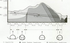
Above all, NATM is not a worst-case design but aims towards adjusting to locally varying conditions as closely as possible. To that end, the anticipated ground conditions are most expediently grouped into several ground classes with distinct characteristics with respect to ground behavior during excavation. Each of these ground classes require a specific type and amount of initial tunnel support that can be designed on the basis of the individual ground properties and other geologic and hydrogeologic conditions representative for that class. By doing so, the design has also to consider, and to simulate, all the specific excavation steps that are pertinent to an individual class (Figure 13).
Various classification systems have been developed during the last decades, and every year more international work shops focus on ground classification as an important tool to simplify the decision-making process on site. To be meaningful, the description of the different ground classes must concentrate on either a geotechnical depiction of the ground characteristics, a structural evaluation of the expected ground behavior during excavation, or an organizational portrait of the appropriate sequence of excavation and support. The latter method permits to directly and indisputably relate the ground class with the safely achievable excavation volume per advance, an approach that comes close to the contractor's practice to estimate the cost of excavation.
For the whole system to work properly, especially when the contractor gets paid for the initial support in the quantity actually placed, the special provisions need not only to clearly and unmistakably describe the different soil or rock classes, but also the specifics of the related excavation sequence, such as: allowable size and depth of advance for each heading (top, bench, invert), time or distance from the face within which the initial support has to be completed, etc. In other words, while the design frames a certain support sequence for each drift to minimize the necessary initial lining, the drawings and special provisions must specify this sequence in a clear, concise, and complete manner to guarantee the validity of the design assumptions.
Only by observing the specified sequence one can expect the actually induced load redistribution process and the developing stresses to closely resemble those computed and the initial lining to be adequate. And as an important side effect, it generally also assures that the contractor applies only that amount of initial tunnel support that is truly necessary; doing this in order to advance swiftly instead of following excavation steps that would be tedious and, at the same time, inconsistent with the encountered conditions.
PVC-Membrane and watertight Concrete in the UK.
Characteristically, the final decision about the appropriate support is made on site and by the key engineers involved in the construction. They will render this decision on the basis of their experience with similar ground conditions as well as with the foregoing excavation on the same site, but always with the help of the various support and ground classes that has been drafted during the design.
And of course, here the question of responsibility appears again, menacing as always: Who is the one to blame for setbacks, even failures? Quite naturally, as it appears, the owner is responsible for whatever conditions are encountered in the ground, because he will ultimately have to pay for the uncertainties of the geologic forecast; the engineer is responsible for providing a functional set of support measurements to choose from when certain defined and foreseeable conditions are encountered, and molding his design into executable contract documents; the contractor finally is responsible for choosing the appropriate support on the basis of the provided design, as he is responsible for the safety and the quality of the work".
So, on site and face to face with the rock or soil encountered, the contractor's chief engineer and the Resident Engineer will evaluate the actual ground conditions on a day-to-day basis, and discuss the appropriate steps to take. They will have to choose from the variety of ground or support classes provided by the design, and the contractor's representative will finally propose the support class he considers appropriate and safe.
It is the in the interest of both parties involved in this process to reach a consent, because the contractor will be anxious to proceed swiftly and the inspecting engineer will need to confirm the contractor's decision in order to approve payment accordingly. But what if they don't agree? In a well-cast contract this should
not only be a remote, though possible, situation, there must also be a provision to resolve this obstinate circumstance. For the benefit of both parties, there must be a procedure that permits to continue construction work without interruption, and to keep the contractor's cash-flow running. This procedure must accomplish the office of arbitrating a technically correct and practicable agreement without changing the original distribution of the respective responsibilities.
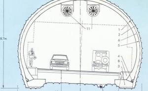
Booster Fan System as used for the Lehigh Tunnel No.2.
To that end, a Disputes Review Board is currently being installed at the Lehigh Tunnel No.2 in Pennsylvania, the first highway tunnel in the U.S. to be constructed by use of NATM, to render assistance in case of disagreement about rock classification and related support. The contract is based on unit prices for excavation in five different rock classes as well as for the various types and amounts of initial tunnel support. Contract documents precisely describe excavation and support sequences and related support items for each rock class. The contractor will have to propose the initial tunnel support he deems necessary for the structural integrity of the lining the safety during construction.
In case the resident engineer agrees with the proposed classification and the respective support items, he simply confirms that the contractor will get paid accordingly. Supposed he feels the support as not being sufficient, he may require heavier support, i.e. a higher rock class, to be applied. Although the client will carry the higher cost related to that, the contractor will not be released from his responsibility for safe tunneling. However, if the client's representative feels strongly about a less heavy support doing the job, he could not require a lower support class to be used that without assuming all responsibility for the safety during construction.
In that case, he will disapprove the contractor's request for parallel payment but will accept payments to be made according to the lower classification that he believes to be appropriate. While the contractor has to apply whatever he considers necessary for the immediate safety and the integrity of the initial support, he may call for arbitration by the Disputes Review Board. This board - it consists of three members: two being nominated by either of the involved parties and accepted by the other, the third one jointly selected by the first two members - will then decide on the basis of the geologic documentation and detailed monitoring results, whether the initial tunnel support applied by the contractor was justified or not. If the decision is 'Yes,' then the client will pay the difference between both rock classes to the contractor by revising the engineer's disapproval. In case the decision is 'No,' no additional compensation will be granted. The contractor may still proceed to legal arbitration, although his chances to succeed will be minimal.
TENDER TREATMENT
There is one particular tool, though, that will help to fine-tune the reasonability of any decisions with regard to the tunnel support: the detailed monitoring program. Observation of the ground movement, of lining deflection, and of stresses within the tunnel lining will tell a lot about whether or not the applied support is effective and reasonable by comparison with the computed values for the selected rock class. Once some hands-on experience with the local ground behavior is collected, it will manifest the semi-empirical nature of NATM: the ability to gain through experience! Decisions about the appropriate tunnel support will be made with ease, and disputes will hardly come to be on the firm grounds of previous observation and carefully compiled monitoring results.
Eventually, everything falls into place - NATM presents itself as a reliable and economic method for creating underground space. Statements such as ,lack of precedents' and 'difficult contractual situation' should no longer be an excuse for not using it. Nowadays executed in practically all continents, there is still room for alterations, adjustments, additions, as long as one observes the basic axiom of the method: the tender treatment of mother nature. And tunnelers will sympathetically understand that every once in a while a new name tag will be added to this method...
REFERENCES
- Barton N. Lien R. and Lunde J. Engineering classification of rock masses for the design of tunnel support. Rock Mechanics, 6, 1974, 189236.
- Bawa K. S. Development of shotcrete for metro construction in Washington. In Use of shotcrete for underground structural support: proceedings of the Engineering Foundation conference, Berwick Academy, South Berwick, Main, July 1620 1973 (Detroit, Mich.: American Concrete Institute, 1973), 33-49 (Spec. Publ. No. 45).
- Bieniawki Z.T. Engineering classification of jointed rock masses. Trans. S. Afr. Inst. civ. Engrs, 15, 1973, 335-43.
- Brierley G. S. and Cording E. J. The behavior during construction of the Dupont Circle subway station lining. In Shotcrete for ground support: proceedings of the Engineering Foundation conference, Tidewater Inn, Easton, Maryland, Oct 4-8, 1976 (Detroit, Mich.: American Concrete Institute, 1977), 675-711.
- Brunner A. Verfahren zum Bau von Stollen, Tunneln und Schichten in druckhaftem Gebirge. Austrian Patent 197 851, July 15, 1956; filed May 27, 1958.
- Brunner A. Die Spritzbetonbauweise beim Bau von Untergrundbahnen. Ost. Ing.-Z., 9, No.1, 1966.
- Construction Industrie Research and Information Association. Tunneling - improved contract practices. CIRIA Rep. 79, 1978, 70p.
- Deere D. U. Technical description of rock cores for engineering purposes. Rock Mechanics Engng Geol., 1, 1963, 16-20.
- Einstein H. H. et al. Computer-based decision support systems for undergroud construction. In Rapid Excavation and Tunneling Conference, New Orleans, Luisiana, 1987: Proceedings. Jacobs J. M. and Hendricks R. S. eds (Littleton, Colorado: Society of Mining Engineers, Inc., 1987), vol. 2, 1287-308.
- Eisenstein C. D. Edmonton Transit Tunneling Methods. Presented at Rapid Transit Tunneling symposium., Toronto, Sept. 15-16, 1986.
- Gobiet W. Beitrag zur Berechnung von Tunnelauskeidungen. Dissertation, Technische Universitit Graz, 1970.
- Heflin L. H. and Irshad M. Soft ground NATM tunnel designs. Reference 21, vol. 1, 111-29.
- Hoeck E. Geotechnical considerations in tunnel design and contract preparation: 17th Sir Julius Wernher Memorial lecture. Trans. Instn Min. Metal!. (Sect. A: Min. industry), 91, 1982, A101-9.
- Hughes J. NATM drifts at Barrow-upon-Soar. Tunnels & Tunnel!., 19, Dec. 1987, 44-5.
- Muir Wood A. M. Ground behaviour and support for mining and tunnelling: 14th Sir Julius Wernher Memorial lecture. In Tunneling ,79 Jones M. J. ed. (London: IMM, 1979), xi-xxii; Trans. Instn Min. Metall. (Sect. A: Min. industry), 88, 1979, A23-34.
- Mueller L. Felstests zur Ermittlung von Spannungen in-situ. Presented at Institute fur Bodenmechanik und Felsmechanik, Universitit Karlsruhe, Jan. 15, 1976.
- Mueller L. Sauer G. and Chambosse G. Berechnungen, Modellversuche und in-situ-Messungen bei einem bergmannischen Vortrieb in tonigem Untergrund (U-Bahn Frankfurt/Main). Bauingenieur, 52, 1977, 1-8.
- Mueller L. Der Felsbau, dritter Band: Tunnelbau (Stuttgart: Ferdinand Enke Verlag, 1978), 945 p.
- Mueller L. and Fecker E. Grundgedanken und Grundsatze der Neuen Osterreichischen Tunnelbauweise. In Grundlagen und Anwendungen der Felsmechanik: Felsmechanik Kolloquium, Karlsruhe, 1978 (Clausthal: Trans. Tech. Publications, 1978), 247-62.
- Mueller L. Die Bedeutung der Ringschlu lange und Ringschlu zeit im Tunnelbau. In 4th International concress on rock mechanics, Monteux, September, September 2-9, 1979, vol. 1, 511-9.
- Pacher F. and Sauer G. Gedanken zur Auslegung von Tunnelausschreibungen und zum Stand der me technischen Bauwerksuberwachung. Rock Mechanics Supplement 10, 1980, 197-205.
- Peck R. B. Deep excavation and tunneling in soft ground. In 7th International conference on soil mechanics and foundation engineering, Mexico, 1969: proceedings, state of the art volume (Mexico City: Socidad Mexicana de Mechanica de Suetos, 1969), 225-90.
- Rabcevicz L. v. Verfahren zum Ausbau von unterirdischen Hohlriumen, insbesondere von Tunneln. Austrian Patent 165 573, 1948.
- Rabcevicz L. v. Bolted support for tunnels. Mine Quarry Engng, 21, 1955, 111-6, 153-9.
- Rabcevicz L. v. Die Neue Osterreichische Tunnelbauweise. 1. Enstehung, Ausfuhrungen und Erfahrungen. Bauingenieur, 40, No. 8, 1965.
- Rabcevicz L. v. The New Austrian Tunneling Method. Water Power, 1964, 453-7, 511-4, Jan., 1965, 19-24.
- Rabcevicz L. v. Stability of tunnels under rock load. Water Power, 21, 1969, 225-9.
- Rziha F. Lehrbuch der gesammten Tunnelbaukunst, Band lI (Berlin, 1872).
- Sattler K. Osterreichische Tunnelbauweise - Statische Wirkungsweise und Bemessung.Bauingenieur, 40, No. 8, 1965, 297-301.
- Sauer G. Spannungsumlagerung und Oberflachensenkung beim Vortrieb von Tunneln mit geringer Uberdeckung unter besonderer Berucksichtigung der Mittelwandbelastung beim synchronen und asynchronen Doppelrohrenvortrieb. Veroffentl. Inst. Bodenmechanik u. Felsmechanik, Univ. Fridericana, Karlsruhe, No. 67, 1976 (Dissertation).
- Szabo G. The fundamentals for a new strengh-theory (Die Grundlagen einer neuen Festigkeitstheorie) (Wiesbaden, Berlin: Bauverlag GmbH, 1966).
- Teichert B. Spritzbeton (Avegno, Switzerland: E. Laich SA, 1980).
