You are here
Canopied portals for NATM rail tunnel
T&T 9/93
ABSTRACT:
Construction of a twin-track NATM rail tunnel outside Salzburg in Austria is proceeding according to schedule. The tunnel is being built in loose alluvial sands and gravels which are responding well to the NATM method. Canopies consisting of a primary shotcrete shell reinforced with lattice girders and mesh are being constructed at the portals, the northern one being 45m long to accommodate the weight of two roads which will eventually pass overhead with an overburden of only 1m.
The baroque city of Salzburg, birthplace of Mozart, was built in a setting of breathtaking beauty, dominated by the Hohen Salzburg, the mediaeval fortress on the Mönchsberg. The need for communications in the modern world and the ever increasing traffic have meant that many road and rail tunnels have had to be built through the surrounding mountains to facilitate the movement of people and freight.
In today's world, the continent of Europe is being traversed by high-speed railways and Austria is updating its rail system accordingly. Its mountainous terrain dictates the need for tunnels of varying lengths. Currently, there are several such rail projects under construction or in the process of design: the twin-track Rupertus Tunnel is one of them.
Construction of this tunnel, part of the Tauernbahnstrecke between Salzburg and Wörgl to the south, has been expedited to dovetail with the construction of a hydro station which involves diverting the Salzach River near the north portal. Ground conditions for tunnelling are particularly difficult at this location, where soft ground comprising sand and gravels present challenging engineering problems in this environmentally sensitive area.
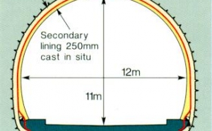
The Rupertus Tunnel, designed to accommodate the Europcan structure gauge requirements, is 330m long with an excavated cross section of 110m2. lt is 11m high by 12m wide. The radius within the alignment of the tunnel is approximately 600m, with a maximum gradient of 8.6 per mille. There are safety niches every 48m on both sides. Maximum overburden is 25m.
The tunnel is being built according to the NATM, as has been the custom with tunnel construction in this part of the world for many years. Consultant for the project is the Dr Sauer Company, with supervision conducted by Tauernplan for the client, the Austrian Railway Authority (ÖBB). Contractor is a JV of Austrian companies Porr, Hinteregger and Alpine.
Excavation method
Excavation is procceding by top heading and bench with a Liebherr 912 backhoe. This highly versatile piece of equipment has an excavator arm that can move through 250°, enabling close control of the tunnel profile. Invert closure takes place every 20 to 50m, depending on the geology.
The tunnel is located in the Salzach River valley, where the ground is composed of non-cohesive alluvial material, mainly sands and gravels with blocks and lenses of silt, which was laid down in the Quaternary era. The glacial material is medium to highly compacted, and near the river banks there are some cemented conglomerate zones.
Main material properties
- Angle of internal friction: Y 32-40°
- Cohesion: c = 0-1.5kN/m2
- Weight: g = 22.0kN/m2
- Range of fines: 5-50 per cent
- Plasticity index: IP 11.0-15.5 per cent
Site investigation
Since the geology in this area is well understood, very little site investigation was deemed necessary. Ten boreholes were sunk to a depth of up to 40m in the mountain, revealing nothing unexpected. The water table is about 6m below the invert, at the level of the river. The ground is of medium permeability with no aquifers.
Small amounts of water are expected in the winter because of rain and snow, but this will drain down channels in the waterproof membrane and be collected in a lateral drainage system at rail level. Old road tunnels in the area are suffering as a result of inadequate waterproofing.
Portals
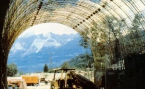
The two portals will be constructed in open cut and provided with canopies, each consisting of a primary shotcrete shell reinforced with Pantex lattice Girders and wire mesh and lined with a PVC membrane with fleece. Only an inside shutter will be necessary. The secondary lining, as in the mined part of the tunnel, will be of unreinforced concrete cast in situ to a thickness of 250mm (Fig 1).
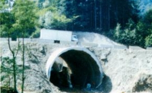
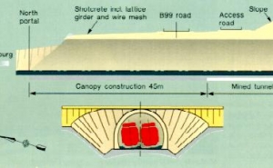
The north portal is the trickiest of the two to construct due to its proximity to the Fritzbach River and the fact that two roads will eventually pass above it with only 1m of overburden (Fig 2). This portal will be 45m long, as opposed to the south portal, which is only 12m long (Fig 3). Work, which started towards the end of May, is to be performed in three phases to fit in with the power station programme.
When Tunnels & Tunnelling was on site at the end of June, the existing road had been diverted to bring plant closer to the face. A stretch of open cut had been dug to stabilise the 65° portal slope by supporting it with shotcrete, wire mesh and five rows of 4m long ground anchors made by Ischebeck, Ibo and Mai-anchor hand drilled at 1 to 1.5m centres.
Some stabilisation of the hillside above this temporary road has also been undertaken. Two invert slabs 12m long and 3m wide have been laid from the portal site across the Fritzbach to form a bridge for the new rail alignment. A waterproof reinforced concrete slab will be laid in the invert of the portal.
Excavation sequence
Logistics dictated that, as work started at the north portal, the mined part of the tunnel should commence from the south. The sequence adopted was to drive the top heading first with the Liebherr 912 for 1 to 1.5m depending on the looseness of the ground.
While the backhoe is hard at work, a Liebherr 551 is simultaneously zooming in, scooping up the loose material and transporting it out of the tunnel in a slick and well coordinated operation. Speed is of the essence to preserve the integrity of the tunnel profile. At the end of the previous round, 4m spiles had been driven around the top of the arch, with a 3m overlap, ready for the next round. In the past it was believed that only metal sheets would prevent unstable ground from collapse, but the Rupertus Tunnel demonstrates that spiles are perfectly adequate with this degree of cohesion, however slight it may seem.
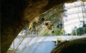
Immediately the top of the heading is cleared, the lattice girders are erected as quickly as possible (Fig 4). This operation is carried out by two men standing on the rocker shovel of the Liebherr 551, which is perched at an angle on the spoil in the centre of the face so that the girders can be precisely located and quickly erected. Dr Sauer pointed out that, in his opinion, this practice was much safer than utilising a mobile platform which, with a weight of only 300kg, was less stable then the 14 tonne rocker shovel.
Another advantage is the ability of the mucker to reverse swifly out of the danger zone in the event of a collapse.
Shotcreting procedure
As soon as the lattice girders are in place, lengths of wire mesh 1.2m wide are installed with an overlap of 200 to 300mm. When this operation is completed, excavator and mucker retire and two men begin the shotcreting by hand to a thickness of 300mm, using dry-mix shotcrete. A basket lift with a platform is used for shotcreting the crown (Fig 5).
The excavation procedure in the crown involves the use of three lasers to deter- mine the tunnel alignment. A five laser approach is also common in Austrian NATM tunnels. Tunnel convergence is measured by surveying rather than tape measurement. Five convergence bolts every 10m monitor convergence and roof settlement in the tunnel.
Deformation was predicted to be in the order of 20 to 50mm and the tunnel is being excavated to allow for 100mm of movement. In the event, vertical settlement is uniform so far at 50mm.
Soil anchors are installed by a 2-boom Atlas Copco 145 jumbo with 4m long booms. After the initial shotcrete support has set, another coat is applied to create a smooth finish for later installation of the waterproofing membrane. The second layer has no structural significance.
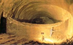
After the top heading has proceeded for, typically, 25m, excavation is halted and work begins on the bench, where excavation proceeds in alternating excavation and support (Fig 6). During the last week of June, speed of excavation was 4m/day for the top heading and 12m/day for the bench. Progress had improved from an average 2.5m/day for a complete ring. The crown had progressed for 177m, the bench for 144m.
The tunnel is formed as a complete shotcreted circle, with the invert temporarily filled in to provide a flat surface for all the paraphernalia of construction. The fill will be removed before the invert concrete is laid. The invert will be levelled off again for final rail installation. As project manager Jenö Rulff said, and he should know: "For me, this profile is excellent. I have never seen a better one."
Teamwork is of the essence in this type of operation, and could not be faulted. Indeed, the speed of operation was quite breathtaking. Fortysix people make up the team altogether for the tunnel, portal and earthworks, plus five senior staff. There are four crews of ten people each, working three round-the-clock shifts, 7 days/wk, with one rotated crew on constant stand-by.
When the north portal is finished, excavation will proceed in top heading and bench, as it did from the south portal, until breakthrough occurs, which is planned for August. The completed tunnel will be lined with a 2mm thick Polyfelt membrane with geotextile fleece backing. A final lining of cast in-situ unreinforced concrete 250mm thick will be installed using 12m long formwork.
When in operation, the tunnel will be ventilated by one Korfmann jet fan, with one noise absorber at each end.
Fitting out of the tunnel and electrical and mechanical work will take place between mid-October and mid-December. Commissioning is scheduled for December'93.
