You are here
Achieving Dry Stations and Tunnels with Flexible Waterproofing Membranes
1st Brazilian Tunnels and Underground Structures Conference, February 29 - March 3, 2004
ABSTRACT
Striving to reduce maintenance and operations cost, more and more owners worldwide are looking for ways to seal their underground structures to prevent the intrusion of water and subsequently creating user friendly facilities for patrons and a comfortable work environment for their maintenance and operations personnel. After several decades of trial and error the flexible membrane waterproofing system emerged as the only suitable waterproofing system for tunnels and underground spaces, due to its capability to resist rheologic, tectonic and earthquake-related movements in the surrounding ground, as well as changes within the structure. The use of this type of waterproofing in underground construction has not only produced a friendlier ambient for the user of public transportation, but has also increased safety in roadway tunnels where deteriorating tunnel structures and the formation of icicles were major concerns for maintenance crews. Besides infrastructure tunnels the flexible membrane waterproofing is today used in utility tunnels and underground chambers which house machinery and equipment sensitive to humidity. The cost associated with the installation of the flexible membrane waterproofing is negligible compared with the cost to replace original installations, cost for leak remediation and increased maintenance hours. Above all, however, stands the importance to minimize the deterioration of concrete and the corrosion of reinforcement by infiltrating water.
HISTORY
Traditional methods to prevent water infiltration into underground structures such as grouting the tunnel lining and the surrounding ground or tiles applied on the inside face of the tunnel lining did not bring the expected results. Therefore, based on Rabcevicz's theory that a tunnel lining consists of two completely separate shells the idea was created to apply a layer between those shells to seal off any intruding water. After promising trials with asphalt mastic membranes and sprayed insulations with glass-fiber reinforcement in the early 1960's these systems never achieved full success. Ten years later flexible membrane waterproofing systems consisting of a non-woven polypropylene geotextile and a high-polymer sealing material were developed in Switzerland and Austria and were utilized throughout Europe with the adoption of the New Austrian Tunneling Method (NATM). In 1983 with the introduction of NATM as a construction contract value engineering change proposal at the Washington Metropolitan Area Transportation Authority (WMATA) the flexible membrane waterproofing system was applied in a United States underground structure for the first time. The successful application and the subsequently reduced maintenance and operation cost encouraged WMATA not only to make this waterproofing system mandatory in all mined underground structures and tunnels, but also to expand its application to cut-and-cover structures. Thus, in the mid 1990's, when WMATA decided to finalize its Mid-City E-Route and its northern extension of the Outer B Route, not only running tunnels, but also cut-and-cover stations, were waterproofed with a flexible membrane waterproofing system. In addition, along the new Mid-City E-Route and Outer F Route, the system was installed at ancillary structures, such as emergency egress shafts and ventilation structures, and in shield driven running tunnels between initial pre-cast element support and concrete final lining. Today the system is also used by the Massachusetts Bay Transportation Authority (MBTA) in Boston, the Dallas Area Rapid Transit System DART and other Authorities throughout the United States at mined tunnels and cut-and-cover structures. An alternative application for the flexible membrane waterproofing is tunnel rehabilitation. Beginning with the rehabilitation of the Felbertauern Tunnel in Austria in 1985 infrastructure tunnels in Europe and the United States have undergone remedial work using this system.
DESIGN
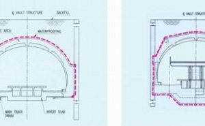
Prior to the design of a flexible membrane waterproofing system the designer has to decide, if an "open" (Figure 1) or "closed" (Figure 2) system is applicable. The main distinction between the two systems is the termination of the membrane at invert level in the open system while in the closed system the membrane is placed circumferentially around the structure. In the open system water reaching the membrane is forced to run within a geotextile or fleece behind the membrane to be collected at perforated pipes, which makes the system suitable for applications at structures above the ground water table or in ground with low permeability, where the water amount expected to be collected is manageable. Manholes at even spacing are designed along the perforated drainpipes to allow periodic cleaning of the pipes. The calcification process of the pipes is slowed down by keeping the entire drainpipe system submerged. The disadvantage of this system lies in the cost associated with the constant discharge of the collected water. This cost will not be incurred by choosing a closed system, which in return requires more skill and effort during installation, especially if ground water pressure comes into play during the placement of the invert waterproofing.
The design criteria for a flexible membrane waterproofing for any kind of underground structure may it be new or rehabilitated has to address the following subjects:
- Materials.
- Preparation of surface.
- Construction sequencing.
- Installation.
- Testing of seams.
- Protection of installed waterproofing during construction activities.
Although individual applications call for special considerations the flexible membrane waterproofing system generally consists of two layers and is installed between initial and final lining of a tunnel. The first layer is a needle punched, non-woven polypropylene geotextile, installed directly against a smooth surface, where smoothness and waviness of the sub-strata are defined by the specifications. The geotextile fulfills a dual purpose. First to cushion the membrane against the pressure applied during the placement of the final lining where the membrane is pushed hard against the sub-strata and second to transport water to the perforated pipes at the membrane toe in an open system. The installation of the geotextile is followed by the installation of the high-polymer membrane of 2.0 to 3.0mm thickness. Today membranes commonly used are a polyvinyl chloride (PVC) membrane or a modified polyethylene (PE) membrane a product developed from low density polyethylene (LDPE) membranes. Both membrane types fulfill the requirements necessary for a successful waterproofing application:
- The waterproofing system must provide a continuous enclosure of the area critical for intrusion of water.
- The imperviousness of the waterproofing must remain permanent despite movements caused by long-term ground behavior, temperature variation, vibration, or shrinking and creeping of concrete.
- The waterproofing must be able to bridge small cracks in the construction surface. It must be able to absorb discontinuous stress variations and, to a certain extent, in-plane forces without being damaged.
- The waterproofing must be resistant to all types of aggressive water, whether from natural sources or contaminated ground, and to biological attacks.
- The waterproofing must be suitable for installation on damp and wet surfaces. It must be easy to handle and to install. Installation must be possible in large quantities at acceptable cost.
- The material must be self extinguishing in case of fire.
- It must be possible to check the waterproofing system for potential damage and easily repair it before the system is covered by the structural concrete (Sauer, Garrett, 1987).
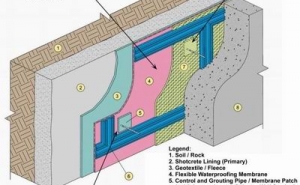
To reduce cost and effort during the repair of an isolated leak once the construction is completed, the membrane waterproofing is subdivided into sections (Figure 3) by water barriers welded to the membrane at their base. The ribs of the water barrier are integrated in the final concrete lining to create an impervious grid around the sections. Leakage is generally detected through pipes running from the waterproofing membrane to the face of the concrete lining and placed in low and high points of each section. Once leakage is detected, treatment usually consists of injecting a low viscosity grout through the lower laying grout pipes, thus creating a second, remedial waterproofing layer between concrete lining and waterproofing membrane.
Other waterproofing systems currently under consideration at underground structures are spray-on systems, bituminous systems and bentonite systems. Each of these systems, however have limited applications at underground structures and does not fulfill all of the above mentioned criteria for a successful waterproofing application. Another membrane based waterproofing system using a high density polyethylene (HDPE) membrane has also not been found suitable for most underground applications due to the rigidity of the material. Chemical grouting, although extremely has only proven successful in cases where the goal was to divert the water rather than to stop the inflow of water and for remedial repair at systems with sections.
Mined Structures
Since the use of flexible membrane waterproofing systems at underground structures originated in mined tunnels this application has not changed significantly over the years. Besides the introduction of sectioning to improve response to localized leaks and BA-Anchors for rebar attachment, not too many modifications were necessary (Figure 4).
BA-Anchors consist of a hard shell insert connected to a soft flap of a material compatible with the membrane and a threaded rod. The insert is installed into a pre-drilled hole in the initial support lining and set in place with epoxy grout. Once the epoxy grout is hardened the flap is welded to the surrounding membrane and the threaded rod is screwed into the insert. This watertight set-up can be used as a fixture for any temporary installation to accommodate final lining installation and etc. Other standard waterproofing details, such as pipe penetration sleeves and termination strips are also used at mined structures. In designing a closed system, special consideration has to be given to the protection of the invert membrane and the build-up of water pressure prior to the invert pour. Ground water pressure build-up has to be dealt with by designing a temporary construction drainage and relief pipe system.
Cut-and-Cover Structures
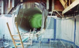
Waterproofing systems for cut-and-cover structures are generally more complex than systems for mined underground structures. The square shape of cut-and-cover structures increases the amount of waterproofing details significantly, since special provisions have to be made at invert to wall and wall to roof connections. Furthermore, open cut construction employs varying support and bracing systems (i.e. soldier pile and lagging, slurry walls, tie-backs, pipe-struts, etc.), requiring close coordination between waterproofing installation sequences and overall construction progress. The biggest concern for a waterproofing system at a cut-and-cover structure, however, is the increased requirement for protection during removal of the bracing system, installation of reinforcement (Figure 5) and during backfilling operations.
At roof slabs of cut-and cover structures the installation process is reversed and water barriers have to be embedded into the roof slab during the roof slab pour. The membrane is attached to the water barriers and subsequently covered with geotextile and protective concrete prior to the backfilling operation. A similar installation sequence has to be applied at free-standing structures detached from the support of excavation. Likewise a water barrier has to be embedded in the structural concrete to terminate the waterproofing membrane near or above ground level. Despite all these requirements, which increase the cost of waterproofing at cut-and-cover structures, the flexible membrane waterproofing system still is the most reliable and cost efficient system.
Rehabilitation of Underground Structures
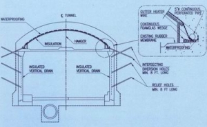
Applying a flexible membrane waterproofing system at a rehabilitation project one has to overcome the basic problem that the water has already entered the structure. Thus the design has to address the collection, diversion and discharge of the infiltrating water (Figure 6). In large seeping areas the collection can be carried out directly at the location of the water infiltration by means of a membrane attached to the structure surface. This is applicable in the tunnel crown or the air duct of an existing tunnel and where post-construction installation of membrane and protective concrete, shotcrete or architectural cladding do not encroach the clearance envelope. Should this space not be made available the water has to be drawn into vertical drains by relief holes, most commonly at the construction joints of the final lining pours. Relief holes and perforated drain pipes not only reduce pressure on the tunnel walls, but also provide a channel to divert the water collected by the membrane from horizontal pipes at the membrane termination to lateral pipes in the invert and ultimately to the tunnel main drain.
In tunnels at higher altitudes where freezing during the winter months becomes a factor, the applied waterproofing membrane has to be protected with insulation boards. Exposed drain pipes or drain pipes close to the structure surface have to be equipped with a heating wire.
INSTALLATION
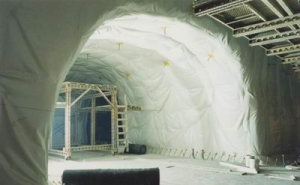
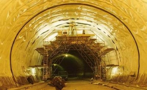
Skilled installers and experienced inspection are two basic requirements for the successful installation of a flexible membrane waterproofing system. Therefore, the contract documents have to specify the minimum experience in the application of this system in underground structures required by the installer. Beyond that the specifications have to address the production and submission of shop drawings, an internal quality control program by the installer, personnel used for the installation and proper installation equipment. The equipment does not only cover the use of hot wedge welders to produce double seams testable with air pressure and hand held hot air guns to weld single seams, patches and water barriers, but also the selection of adequate scaffolding for a membrane installation in a mined tunnel (Figure 7).
Membrane and geotextile are generally produced in sheets of 1.8 to 2.1m width and delivered to the site in lengths equivalent to the circumference of the tunnel above invert level. The geotextile sheet is installed perpendicular to the tunnel axis and attached to the sub-strata with fired fixing nails and washers of a material compatible with the sealing membrane. The pattern of the attachments is carefully chosen since the washers are designed to hold the membrane in place prior to the pour of the structural concrete. Membrane installation starts at the crown of the tunnel and progresses downward welding the membrane to the washers, creating an attachment without penetration of the membrane. Once installed the membrane sheets are connected by double seams which are tested by the end of the shift. The production of an experienced crew for the installation of geotextile and membrane including welding and testing the seams in a 10.0m wide tunnel is between 15.0 to 20.0m per 10 hour shift. The seam layout in cut-and-cover structures is dominated by the geometry of the structure however, wall seams are generally vertical. Water barriers are frequently installed at construction joints to provide additional protection against the formwork at the bulkhead of each pour. During installation, the owners through their construction management team have to provide inspection experienced in the application of this type of waterproofing system. This sets forth that the inspection team is not only familiar with materials, installation and testing procedures, but also with the installation sequence, groundwater management and protection of the waterproofing during construction.
CONCLUSION
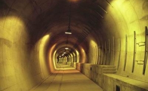
The use of a flexible membrane waterproofing system requires more frequent replacement of rail car air filters due to increased dust levels created by the drier tunnel conditions (J. Donahue, 1998). This constitutes a relatively minor maintenance cost compared to the rewards of a dry tunnel (Figure 8) for the owner and provides him with the ability to project accurately a maintenance budget, which can be achieved without interference to the functional use of the structure.
Since its introduction in the 1970's the flexible membrane system has not only held its status as the most reliable waterproofing system for mined underground structures, but has expanded the area of application to cut-and-cover structures and tunnel rehabilitation projects. It is proven today, that with an enhanced design, skilled installer and experienced supervision the flexible membrane waterproofing system can produce dry tunnels and underground structures under almost any circumstance. This is especially true for projects where the waterproofing is fully integrated in the project design and where the contractor adjusts his construction sequencing according to the requirements of the waterproofing installation.
REFERENCES
- Donahue, J., March 1998. Lesson No. 31. Waterproofing and Its Effect on Operation and Maintenance of Underground Facilities, Federal Transit Administration, Lessons Learned Program
- Mergelsberg, W., Gall, V., Sauer, G., 1996. Achieving Dry Cut-and-Cover Stations, North American Tunneling Magazine
- Sauer, G., Garrett, V.K., 1987. Achieving A Dry Tunnel, Rapid Excavation and Tunneling Conference Proceedings.
