You are here
Pushing the envelope
June 1, 2003
Herndon, VA, USA
Pushing the envelope
REHABILITATION OF THE CAMERON RUN TUNNELS
RETC 2003
Rapid Excavation and Tunneling Conference, New Orleans, LA, June 2003
ABSTRACT
Rehabilitation work at the Cameron Run Tunnels entailed the restoration of seven heavily deformed, approximately 69 m long, steel liner plate supported culverts through a CSX Railroad embankment near Alexandria, Virginia. A custom fabricated expander, equipped with four 200-ton hydraulic jacks on two expansion arms was used to push back the liner plates encroaching into the proposed tunnel profile and install the steel set support. In a second phase the tunnels were then lined with 16 cm of fiber reinforced shotcrete. Geotechnical instruments both in the tunnels and on the railroad embankment were used to monitor the effects of the rehabilitation work on the two CSX Railroad tracks above the tunnels. Freight and passenger trains were required to run uninterrupted and at maximum speeds throughout construction.
INTRODUCTION
In late 1977 the City of Alexandria completed the construction of the seven parallel, 6 m diameter circular tunnels through the existing embankment of the Richmond, Fredericksburg and Potomac Railroad at Cameron Run. The tunnels were built in close proximity (distance at springline is 2-1/2 m) to improve the flow characteristics of the Cameron Run and to allow room for a bike trail along the northern bank of the run. The tunnel design called for No. 3 gage, two-flanged corrugated liner plate support, protected by a field applied asphalt mastic coating and a 7-1/2 cm thick concrete invert. The contractor experienced difficulties mining the tunnels and liner deformations occurred almost immediately after the beginning of construction. The deformations continued after the completion of the construction and in 1994, the City of Alexandria installed timber pile supports in six of the seven tunnels.
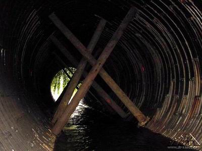
Figure 1: Deformed tunnel with timber pile support.
In 1998 the City of Alexandria decided to undertake the rehabilitation of the tunnels, since propping with timber piles as countermeasure to the ongoing deformations did not improve the long term tunnel stability and resulted in unacceptable water flow conditions. The contract to provide engineering services for the rehabilitation of the Cameron Run Tunnels was awarded to the Dr. G. Sauer Corporation (DSC) of Herndon, Virginia, in October 1998, because of their innovative approach to rehabilitate the tunnels.
ENGINEERING AND DESIGN WORK
The engineering phase for the tunnel rehabilitation consisted of several steps, beginning with a field investigation, an evaluation of the investigation’s findings and the production of a design, including contract drawings, specifications, structural computations, hydraulic analysis, construction schedule and construction cost estimate.
Field Investigation
The purpose of the field investigation was to gather information to produce as-built drawings and a technical report which would become the basis for any further design development. The field investigation at the Cameron Run Tunnels was conducted in fall of 1998 and featured a surface and a sub-surface investigation.
Surface Investigation.
The surface investigation was carried out in four steps and included topographic survey, tunnel profile scanning, tunnel walk-through inspection and probe drilling in the concrete inverts. The results of the topographic survey and tunnel profile scanning were used to plot the exact location of the tunnels and to determine location and degree of the deformations in the individual tunnels. The walk-through inspection was performed to map the location and extent of any corrosion of the steel lining above the concrete invert level, to locate taper courses, shims and breaking sets in the liner plates, and to determine number and location of timber pile supports in the tunnels. The probe drilling in the invert was mainly performed to gain information about the as-built thickness of the concrete slab.
Sub-Surface Investigation.
The sub-surface investigation was conducted to determine the geotechnical condition of the man-made earth fill embankment surrounding the Cameron Run Tunnels. This investigation included a geotechnical test boring program and a probe boring program. The geotechnical test boring program consisted of three hollow stem auger borings drilled between the railway tracks from the top of the embankment to approximately 1-1/2 m below the tunnel inverts. The collected samples were sent to a laboratory for subsequent testing. Standard penetration tests according to ASTM D1586 were conducted on site. The probe drilling program’s main purpose was to evaluate the conditions behind the liner plates, especially in the areas of deformations. The presence of grout, voids or foreign objects, such as wood, was of interest to the engineers. For that purpose, 97 holes were drilled through the steel liner and subsequent to a visual inspection, a non-standard penetration test was performed.
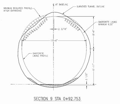
Figure 2: Existing tunnel profile versus proposed tunnel profile in Tunnel No. 2.
Findings
The findings of the sub-surface investigation showed that the man-made portion of the railroad embankment above the springline of the tunnels comprises of 9 m thick medium dense granular soils with silt and clay. These hand-compacted soils are overlaid by 2 m of railroad ballast. Below springline there is a 1-1/2 m thick layer of Terrace Deposit which lies between the railroad embankment’s fill and the Potomac Group Sand. Cementitious grout, injected through ports during construction to fill voids between the liner plates and the surrounding soil was mainly present at springline level and below. Small voids above springline were also detected.
The most common deformations observed were bulges at the rib to crown interfaces of the tunnels, which in Tunnel No. 2 were so severe that they formed cusps. With the exception of Tunnel No. 1, the most northern tunnel, all tunnels showed this type of deformation with varying severity. Timber pile supports of diameters between 35 cm and 65 cm were installed in the worst areas of Tunnel No. 2 through Tunnel No. 7, with an average spacing of 2 m. The timber piles spanned radial from the top of the concrete invert to the deformed areas of the tunnels. Apart from the bulges, ovoid tunnel shapes, sometimes rotated to the left or right side indicating the difficulties during mining, were the most common deficiency.
The use of breaking plates, shims and taper courses in various tunnels revealed the efforts to correct vertical and horizontal misalignments, as well as, out of round tunnel shapes. The overall appearance of the 45 cm wide and 125 cm long liner plates and the bolted liner plate connections was good.
Rehabilitation Design
At the beginning of the design phase the most appropriate and economical way to rehabilitate the Cameron Run Tunnels was evaluated. This was achieved by comparing various rehabilitation methods with the established hydrological, structural and fiscal requirements. In addition it was necessary to produce a construction staging plan, which would allow water to flow through at least three tunnels during construction.
Rehabilitation Method.
Based on the information gathered during the field investigation and the design parameters, technically less sound approaches, such as No Rehabilitation or Internal Relining of Deformed Structures were dismissed. Re-Mining of the tunnels was deemed too costly, and also excluded from the options. DSC’s proposal of a new Internal Lining with Jacking (Expanding) was considered the most favorable rehabilitation approach and further research revealed that a finished shotcrete internal lining, after expanding where necessary, would fulfill all of the following design criteria:
• 5-1/2 m finished diameter (hydraulic requirement)
• removal of all cusps in the liner plates (structural requirement)
• optimization of final liner thickness and jacking length (fiscal requirement)
Construction Staging.
Due to the river flow requirements established by the City of Alexandria a minimum three tunnels had to be open for free water flow at all times during the rehabilitation period. As a result the rehabilitation work at the Cameron Run Tunnels was divided into two phases. The first phase foresaw the closure of Tunnels No. 1 through No. 4 by means of upstream and downstream sheet pile walls. The second phase involved the closure of Tunnels No. 4 through No. 7 after re-arranging the river diversions and building a temporary, elevated access road along the downstream tunnel portals of Tunnel No. 1 through Tunnel No. 3.
Design Considerations.
In order to determine the lining support design and expanding forces, design calculations were carried out. The calculations showed that W6 X 20 steel sets installed at 90 cm intervals and with an average distance of 10 m from the upstream and downstream portals of each tunnel provided sufficient support prior to and after the expanding operation. For the expanding operation a mobile, hydraulic double expander with four free rotating, diagonal arms and 100 ton hydraulic jacks on both ends of the expander arms was foreseen. This jacking device would have sufficient strength to push back the deformed liner plates in all areas identified, which amounted to approximately 50% of the total accumulated tunnel length. Expanding could only proceed once steel sets were installed in the tunnel to be expanded and the adjacent tunnels. The design also provided the option to expand a tunnel, once the adjacent tunnel’s shotcrete lining had reached the required 28-day strength. This option was deemed more time consuming; however, it eliminated the installation of temporary steel sets. These steel sets were only installed to provide stability during expanding and had to be removed prior to the placement of the shotcrete lining. To provide long term stability to the tunnels and to achieve a smooth inner surface, a steel fiber reinforced shotcrete liner with a compressive strength of 27.6 N/mm2 was designed. The shotcrete was to be flush with the inner flange of the steel sets, where applicable and otherwise had a minimum thickness of 16 cm. The design also foresaw the coating of the exposed inner steel set flanges with corrosion protection and the installation of a 7-1/2 inch thick invert pad to protect the structural invert shotcrete and steel sets from abrasion and corrosion. To minimize friction the design required a trowel finished shotcrete lining and invert pad surface.
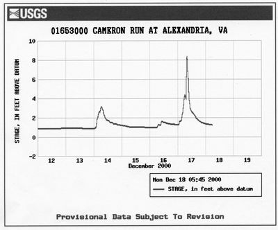
Figure 3: Rise in Cameron Run water level during heavy rain.
CONSTRUCTION
The rehabilitation work at the Cameron Run Tunnels was awarded to the low bidder, Merco, Incorporated of Lebanon, New Jersey, in October of 1999. Work began in March 2000 and was completed by June 2001. The original 14 months contract was extended by two months to complete additional work requested by the City of Alexandria to improve the flow characteristics of the Cameron Run by placing concrete aprons and rip-rap at the tunnel portals.
The contractor chose crib walls and cofferdams rather than the designed sheet pile walls to protect the work area. The height of the crib walls was restricted to 2 m above river bed elevation to avoid a flooding of the bike trail on the north bank of the Cameron Run. Upstream monitors triggered a potential flood-alert alarm to allow for evacuation of the crew and equipment relocation if necessary. These monitors proved especially effective during heavy rainfalls when the water level in the run was raised above flood stage levels in less than two hours.
Crucial to the entire project was monitoring the effect of the rehabilitation work on the two CSX Railroad tracks above. Freight and passenger trains were to run uninterrupted and at maximum speeds throughout construction. Maximum allowed settlement set by the CSX Railroad Engineering Department at track level was 2.54 cm. A total 135 geotechnical instruments were installed in all seven tunnels and at the railroad embankment to monitor ground movement. Work on the tunnels was coordinated with CSX Railroad from the start and the construction management team provided weekly settlement monitoring reports to CSX’s Engineering Department. In addition a CSX watchman/flag-man was assigned to the site for safety purposes and to further monitor the rails. Expansion of the deformed culverts was completed successfully within the track level tolerance and with no measurable movement inside the tunnels. Only once during construction did CSX resurface the tracks, a routine maintenance operation to lift the rails and repack ballast underneath.
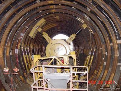
Figure 4: Steel sets with wood wedges during expanding (jacking).
After construction of upstream and downstream crib walls and cofferdams, the contractor started with the rehabilitation work in Phase 1 (Tunnels No. 1 through No. 4), by removing the concrete invert. The steel sets were then placed at 90 cm centers as per the design. In most cases the contractor opted for expanding against a fully cured final shotcrete lining, rather than installing temporary steel sets. The steel sets were blocked against the corrugated liner plates with hardwood wedges. The hardwood wedges were replaced by steel wedges after expanding and prior to the shotcrete application. The sets, which typically comprised of seven segments, were installed with two temporary filler pieces at the springline. The transition from pre-expanded to post-expanded sets was accomplished by replacing the temporary filler pieces with longer, final pieces after expansion to the designed shape. The final filler pieces were factory made, which ensured the proper dimensions of the opening after installation.
The expander was fabricated for Merco, Incorporated by Elgood Meyo and was equipped with four-200 ton hydraulic jacks on two expansion arms rather than the four arms specified. For transport and set-up the expander was mounted on a loader and special shoes on each end of the arms allowed the expander to push back the lining on both sides of a steel set. At the same time smaller jacks mounted on brackets attached to the steel set above and below the filler pieces, pushed the upper half of the separated steel set into place to provide adequate space for the final filler piece. The contractor expanded 230 steel sets in 64 shifts which resulted in a rate of 3.6 rings per shift, quite an achievement for such an innovative technique. Conditions such as the density of the surrounding material, the presence of grout in the soil, and the magnitude and type of deformation influenced the rate of expansion. The maximum expanding (36 cm) was required in Tunnel No. 2, which showed the largest deformation. The heaviest deformed section of Tunnel No. 2 (10 m long) was expanded in two consecutive runs to avoid tearing of the steel liner and possible ground loss.
The final shotcrete lining contains 35 kg/m3 of Novocon Fortex steel fiber and is dosed with MBT Meyco SA160 accelerator. The wet-mix was field-tested extensively to confirm the required strength and, more importantly, to synchronize the feed of the accelerator into the sprayed volume of shotcrete. Shotcrete was being applied using a Reed pump with a maximum 24-stroke per hour pumping capacity. Water reducers kept the water-to-cement ratio at design value to maintain shotcrete strength. During severe cold weather, both portals of the shotcreted tunnel were sealed, and the tunnel heated to near 15oC. Cores from the sprayed liner confirmed that 7-day and 28-day strengths were at or exceeded requirements. Some 2,900 m3 of shotcrete were applied in total at an average rate of 5 m3 per hour. Where necessary, shotcreting was kept at least two tunnel diameters behind the expanding activity in the adjacent tunnel to avoid disturbing the curing shotcrete and to avoid weakening and cracking of the shotcrete.
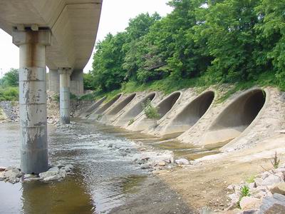
Figure 5: Downstream portal of Cameron Run Tunnels after Rehabilitation.
The original contract amount of $3.56 million was increased to $3.80 million based on additional work requested by the City of Alexandria. No other changes of any significance were required. Contingency items in the unit price contract were mainly used to compensate the contractor for unforeseen work and weather related delays. Although there was no partnering arrangement set-up between the owner, DSC’s construction management team and the contractor, the work was executed in a cooperative way with frequent discussions between the involved parties to coordinate and solve technical, administrative and fiscal issues.
CONCLUSIONS
The rehabilitation of the Cameron Run Tunnels was a successful project due to balanced approach in the design between solid engineering and innovative techniques, as well as, foresight by the City of Alexandria by investing the funds necessary to achieve long term stability of the tunnels. This is especially important, considering the sensitivity of the CSX Railroad tracks above the tunnels and a Metro rail bridge within meters of the downstream portals. It was also successful because all involved parties were willing to contribute their part to move the project forward. From a technical perspective it has to be said that the core of the rehabilitation concept, the controlled pushing back of the deformed liner plates worked as expected. It should, however, not be forgotten that the contractor’s acceptance and full support of the innovative concept was the biggest reason for the project’s success.
REFERENCES
Wallis, S., 2000. “Rail underpass rehabilitation”, T&T North America, June 2000.
Alhussaini, H., Egger, K. and Baker, E., 2001. “Complete transformation for the Cameron Run culverts”, T&T North America, May 2001.
Fortner B., 2001. “Pushing Back”, Civil Engineering, June 2001.
Mergentime, S. K. and Gause, C., 2002, “Cameron Run Tunnel Rehabilitation”, Norwegian Sprayed Concrete Conference, Proceedings 2002.