You are here
Shotcrete Lining Design Concepts for new and rehabilitated Tunnels
April 14, 1999
Sao Paulo, Brazil
Shotcrete Lining Design Concepts for new and rehabilitated Tunnels
Shotcrete for Underground Support VIII, Eighth International Conference, April 11-15, 1999
ABSTRACT
Today’s refined knowledge about ground behavior and numerical modeling as well as improved sprayed concrete technology provide the basis for an ever increasing implementation of shotcrete for initial and permanent tunnel linings. Ground - structure interaction modeling and shotcrete section design is linked to the full appreciation of ground conditions, complex load and stress re-distribution processes and the design of a practical and appropriate excavation and support sequence. A series of shotcrete lining application and design concepts is described.
1. INTRODUCTION
The many computational approaches available for the design of tunnel linings may be divided into three major categories. These include empirical, analytical and numerical procedures. While the empirical and analytical but also numerical procedures, when relying on embedded frame analyses, typically have their place on the conceptual and preliminary design levels, numerical methods using finite element and difference analyses are the preferred tools for detailed designs of shotcrete linings in particular when dealing with complex underground construction tasks. In contrast to other methods finite element and difference methods enable a description of the underground as a continuum with geotechnical characterization. Based on this advantage to incorporate geology and hydrology, overburden depth, size and shape of the tunnel as well as the excavation method proposed the finite element and difference methods remain the preferred tools for tunnel design purposes at the detailed design level and for complex problems.
Even the most sophisticated numerical methods, however, depend in terms of predicting ground lining interaction highly on the assumptions made and therefore on the experience of the design engineer. Knowledge of principles of ground behavior as a response to the tunneling process is of greatest importance in order to achieve good comparison between model and reality. The review of any tunnel lining design by means of numerical computations calls for the review by an experienced tunnel engineer. With this system in place the first step toward an economic and safe lining design is made.
The paper presented relies on the use of case histories to lay out a wide range of aspects and assumptions made for shotcrete lining designs. A review may aid in a decision making process for other relevant shotcrete lining designs. The case histories include design for the construction of new tunnels through soft ground, for complex three-dimensional underground junctions of varying space requirements, for refurbishment of tunnels and re-mining of ground for the purpose of tunnel widening.
2. SHOTCRETE INITIAL LININGS FOR TUNNELS
2.1 Shotcrete Initial Lining for a new Tunnel - London Bridge Underground Station
General
Metro underground stations form complex tunnel schemes and are, in most of the cases, located in urban areas. Soft ground conditions, shallow cover above the tunnels and numerous surface and subsurface structures require excavation methods as well as support methods that are settlement limiting. In addition to ground loads and surcharge loads, settlement compensating systems such as Compensation Grouting apply additional localized loads onto the tunnel lining. During construction of adjacent or crossing tunnel drifts, additional ground loads are transferred onto existing tunnels due to stress re-distribution in the ground.
For the design of such underground schemes, two key requirements have to be observed:
- The excavation and construction sequence must minimize the initiation of settlements, and
- the tunnel support linings must provide early support while withstanding the intermediate and medium term ground loads.
The support system utilized shall be flexible enough to be installed at any time during tunnel excavation or after finalization of an excavation increment but, also, shall not involve bulky equipment that obstructs access to the tunneling face or requires major maneuvers to get ready for support installation. The latter applies in particular for tunneling under confined space conditions.
The above criteria and constraints particularly applied for the construction of the new Jubilee Line London Bridge Underground Station, a project of London Underground Limited (LUL), UK.
Ground Conditions and Surroundings
All tunnels with a shotcrete lining for initial or permanent support are located in London Clay, an over-consolidated tertiary clay.
Figure 1: Plan View of Tunnels at London Bridge Underground Station supported with Shotcrete Lining.
Design Parameters used for London Clay:
γ = 19.5 kN/m3
E = 95.0 MNm2
Cu = 180 kN/m2
Φ = 0°
where:
γ = bulk density
E = Modulus of elasticity
Cu = Undrained cohesion
Φ = Undrained friction
The London Clay displays blocky behavior during and shortly after excavation. Monitoring data indicate increase of tunnel shotcrete lining stress. These increases are either steady or transient generated by ground loads increasingly acting upon the lining after installation or other influences, such as construction activities in close vicinity or Compensation Grouting. Long term monitoring carried out at tunnel linings in London Clay revealed a steady increase reaching a maximum stress level equivalent to 60% of full overburden load after approximately 19 years (D. Barrett et al, 1994).
As can be seen from the above plan view, a series of tunnels were constructed in close vicinity to each other. These tunnels were excavated in sequence such that the previously built structure was influenced by the construction of a near underground opening (K. Zeidler and V. Gall, 1997)
The London Clay is overlain by water saturated gravels and man made fill. Ground cover above station tunnels is approximately 25 m.
At and below ground surface numerous buildings and utilities are located. These surface and subsurface structures are sensitive to differential settlements that occur during tunnel construction. Ground deflection and ground settlements resulting from tunneling were partially compensated by Compensation grouting above the tunnels. The zone treated with Compensation grouting was approximately 2 to 3 m clear above the station tunnels’ roof. Compensation Grouting and the loads transferred onto the tunnel linings had to be considered during the shotcrete lining design.
One particular situation was selected to be described herein as example representative for shotcrete lining considerations for this station. The construction of the 4-way crossing, as displayed in the Plan View (Fig.1), instigated a complex ground loading scenario on the tunnel linings involved.
The previously constructed Eastbound Pilot Tunnel (Pilot Tunnel) / Eastbound Running Tunnel (Running Tunnel) was in place for several weeks when the Interlocking Machine Room (IMR) and the continuation tunnel to the West Ventilation Tunnel were built. The Pilot Tunnel was approximately 5.4 m wide and 5.2 m high and supported with a 150 mm thick shotcrete lining. The excavation cross section of the IMR is approximately 8 m wide and 8.6 m high whereas the West Ventilation Tunnel (Vent Tunnel) continues from the IMR with an approximate width of 7.8 m and 8.4 m height. Both tunnels were initially lined with 300 mm thick shotcrete. The shotcrete lining of the IMR was thickened to 350 mm in the area of junction with the Running/Pilot Tunnel and the West Bound Station Tunnel. The break-out into and the connection to the Westbound Station Tunnel was constructed later from within the IMR.
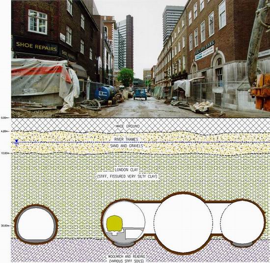
Figure 2: Ground Profile and Surface Structures.
Excavation and Support Sequence
After the suspension of all NATM work at London Bridge Underground Station following the Heathrow collapse had been lifted, a new design had to be developed that set out the following sequence. The excavation and support installation proceeded from the Westbound Platform Tunnel towards the Pilot Tunnel in a top heading, bench and invert excavation sequence. The length of the individual excavation increment was limited to 1 m in the top heading and 2 m in bench and invert. The domed top heading face advanced approximately 2 m ahead of the inclined bench and invert face. This sequence is based on a typical softground excavation and support sequence that takes short term spacial stress re-distribution in the ground surrounding the tunnel into account. The shotcrete lining was always sprayed to its full design thickness before the next excavation round in sequence was commenced. The shotcrete shell was reinforced with two layers of welded wire fabric. Reinforcement was connected across construction joints (between top heading and bench and invert and the individual excavation rounds) by rebars. Additional longitudinal reinforcement was installed at the bottom of the top heading’s shotcrete shell.
Prior to the approach of the IMR construction face at the Pilot Tunnel, the Pilot Tunnel was backfilled up to its springline with muck. Upon arrival at the existing Pilot Tunnel, the standard construction sequence was changed insomuch, as the bench and invert excavation was completed with the full shotcrete invert closure in approximately 2.5 m distance from the Pilot Tunnel springline. The top heading if the IMR intersected with the Pilot Tunnels crown and was progressed beyond the Pilot Tunnel’s crown. During the excavation of the top heading, the IMR shotcrete lining was connected to the Pilot Tunnel shotcrete lining. After completion of 4 excavation rounds of top heading, the IMR’s bench and invert excavation and support was continued to approximately center of the Pilot tunnel while the shotcrete shells were connected to each other simultaneously. The alternating top heading, bench and invert construction sequence was then resumed until the temporary headwall was reached that formed the start-up for the later West Ventilation Tunnel development.
Figure 3: Schematic Construction Sequence for the Interlocking Machine Room.
After the IMR’s shotcrete lining gained sufficient strength (25 N/mm2, equivalent to approximately 7 days strength), the breakout for the Eastbound Platform Tunnel commenced. Due to the intersection geometry and the tunnels’ alignment, the initial step of the breakout was formed by the construction of two top heading excavation rounds to form a 400 mm thick shotcrete collar to stiffen the IMR shotcrete lining. Completion of the shotcrete collar around the entire perimeter of the breakout opening was facilitated by the alternating bench and invert excavation for two rounds each. A temporary headwall was constructed subsequently that connected to the Pilot Tunnel remainder while leaving access to the Pilot Tunnel.
Design Approach
The tunnel geometries, alignments and general construction sequence were pre-defined prior to commencement of the detailed design of the excavation and support method. The Pilot Tunnel was in place, tunnel geometry and alignment was ruled by LUL’s operation requirements and due to construction program constraints, the IMR had to be excavated heading towards the Eastbound Pilot/Running Tunnel.
For design purposes, the London Clay is considered relatively uniform in condition and behavior. Observations from previous tunnel constructions revealed that the above design parameters in combination with the numeric models produced results comparable to the actual on-site conditions.
The following material parameters were used for the design of the shotcrete linings:
Shotcrete:
fcu = 25.0 MN/m 2
Ec = 10,000.0 MN/m 2 (‘green shotcrete’)
Reinforcement:
fy = 500.0 MN/m 2
Es = 200.0 MN/m 2
where:
γ = specific weight
Ec/Es = Modulus of elasticity concrete/steel
fcu = ultimate design strength
fy = Yield Strength
Figure 4: Schematic Construction Sequence for the Breakout into The Eastbound Platform Tunnel.
Partial load factors according to Ultimate Limit State design requirements were used.No surcharge loads were considered for the load cases analyzed for the initial lining.
Monitoring data taken during the construction period suggest that single tunnel lining stresses steadily increase during the continuation of tunneling until a maximum level is reached after 3 to 4 days after lining installation. This maximum level of lining stress is equivalent to approximately 8 to 28% of full overburden load (P. Groves and A. Morgan, 1997) and slowly increases further during the following years. The levels given reflect the percentage increase from a 5.3 m to a 8.6 m span tunnel.
Lining stress monitoring during tunneling stoppages indicated that a lining stress level equivalent to approximately 8% of full overburden is rapidly reached after approximately 1 to 3 days after installation. The stress developing after that period was observed to be either very slowly increasing, transient increasing or even decreasing to approximately 2% equivalent full overburden (observation period 80 days). Lining stress reading curves displayed a distinct and sudden increase after restart of tunneling.
For design purposes, the worst monitoring results were used as basis to assess short term stress levels in shotcrete linings caused by interaction between mining activities and existing tunnel linings.
Prior to numeric modeling and design of the shotcrete supports and their behavior, an assessment of the most likely effects and interaction between the various construction activities was carried out for intermediate and final construction stages.
Approach of the IMR to the Pilot Tunnel
As with all tunnel excavations, the excavation of the IMR causes disturbance of the initial stress regime in the ground surrounding the progressing tunnel drift. Soil extraction for the tunnel removes the in-situ support to the surrounding ground. For the short period from excavation until support installation the ground has to support itself over the tunnel width and the length of an excavation round. This process leads to ground deflection (‘collapsing cavity’), relaxation of and stress re-distribution within the ground. Due to this mechanism, the stress path pattern is changed in the ground, a spherical area of less stress than in the virgin ground is generated in close vicinity surrounding the progressing tunnel face, whereas areas with higher stress levels (stress concentration) are initiated towards the external parts of this stress bulb. This zone influenced by tunneling progresses with the tunnel construction face through the ground. From past experience in London Clay and similar material and from numerical simulation, it was known that the stress bulb reaches approximately 0.5 to 1.0 times the equivalent of the tunnel width ahead of the tunnel face. During tunneling stoppages, it was observed that, due to creep and stress re-distribution effects, loads recommence to act upon the linings within the low stress zone after 1 to 3 days (see above).
The construction of the 4-way crossing was expected to be finished within 2 to 3 days after arrival at the Pilot Tunnel. When the IMR excavation approaches the Pilot Tunnel, it was expected that additional loads in the range of approximately 50 % of short term loads (approximately 14% of full overburden load) will affect the Pilot Tunnel shotcrete lining as a result of load re-distribution ahead of the advancing IMR tunnel face. At the same time, the lateral support towards IMR was reduced due to the IMR excavation while the full lateral ground load acted onto the distal sidewall of the Pilot Tunnel. The shotcrete lining design and installation was carried out prior to the arrangement and design of the IMR. Therefore, the Pilot Tunnel support design did not take these additional and unbalanced loads into account. By checking the Pilot Tunnel lining capacity against the expected additional loads, it was found that the lining would be adequate. While it was not expected that the additional loads acting upon the Pilot Tunnel would cause distress of the lining, deformations of the Pilot Tunnel lining were expected, that result in ground deflections, which may adversely influence the soil properties in this area. To avoid excessive deformation and undeterminable influence on the ground properties, it was decided to backfill the Pilot Tunnel to its axis level.
Intersection of the IMR Top Heading with the Pilot Tunnel Crown
During the progress of the IMR top heading across the Pilot Tunnel the Pilot Tunnel’s roof was removed successively with each excavation round. Immediately following the excavation the shotcrete lining for the IMR top heading was installed and connected with dowel bars to the Pilot Tunnel shotcrete shell. During the design, it was assumed that stress acting within the Pilot Tunnels shotcrete shell would be re-distributed around the opening and temporarily borne by remaining the Pilot Tunnel shell in interaction with the backfill and soil wedge left in place by the stopped IMR bench/invert progress. The temporary stage would last until the IMR shotcrete lining is connected to the Pilot Tunnel shotcrete shell and the IMR shotcrete had gained sufficient strength such that a stiff three dimensional interconnected support system (cross) was established. Shotcrete early strength, lining thickness and the excavation sequence were designed such that, based on the above monitoring data, a 48 hour period was considered adequate for the shotcrete to gain sufficient strength to carry the returning loads.
The subsequent excavation of the IMR bench and invert would eliminate one sidewall and parts of the invert of the Pilot Tunnel. Simultaneously, the IMR shotcrete support would be connected to the Pilot Tunnel shotcrete shell replacing the removed support of the Pilot Tunnel. During the period of IMR construction the backfill was considered to provide additional support to the distal sidewall of the Pilot Tunnel to avoid lining deformations. Furthermore, the previously established stiff connection between the IMR top heading and the Pilot Tunnel shell would provide additional support to the distal sidewall of the Pilot Tunnel.
The Pilot Tunnel shotcrete lining was checked for loads that may potentially be transferred from the IMR lining through the connection into the Pilot Tunnel lining. Due to thickness and inherent stiffness provided by the 350 mm thick IMR lining, it was assessed that maximum 10% of its design stress would be transferred into the Pilot/Running Tunnel lining at each connection. This stress transfer may occur through deformations of the IMR lining resulting from returning ground loads after finalization of the 4-way crossing and from the initial stages of the breakout for the Platform Tunnel (see below).
Construction of the Temporary Headwall
The construction of the headwall was not considered to affect the Pilot Tunnel/Running Tunnel shotcrete lining, since no excavation advance was required to install the temporary headwall. For reasons of conservative design, the contribution to the shotcrete lining provided by the temporary headwall was ignored.
Breakout from the IMR into the Westbound Platform Tunnel
The removal of the IMR support to establish the shotcrete collar at the connection to the Eastbound Platform Tunnel generated an opening that was equivalent to the excavation width of the Eastbound Platform Tunnel (8.6m). The stress originally acting within the removed part of the support had to be distributed around the opening within the remaining section of the IMR shotcrete lining. The excavation for the collar was not expected to transfer additional loads onto the tunnel lining, due to the short term self supporting capability of the ground. The shotcrete shell structure was numerically checked whether it would be capable of sustaining the additional stress due to the distribution around the opening.
To extend the shotcrete collar around the lower half of the opening, the IMR’s shotcrete support was removed in the bench and invert area. Similar to the situation for the upper half, the stress contained within the removed part of the shotcrete had to be redistributed around the opening into the shell remainder. The previously installed upper part of the shotcrete collar contributed to the strengthening of the shell.
Effect of the Construction of the Eastbound Platform Tunnel
It was considered that during the course of further excavation advances in the Eastbound Platform Tunnel, the additional ground loads would be shed backwards onto the IMR and the junction structure. Based on monitoring data from previous large diameter tunnel constructions in London Clay and similar ground material, the magnitude of additional loads being transferred back was assessed not to exceed 50 % of the short term load as monitored (approximately equivalent to 14% of full overburden load). The IMR and junction shotcrete support lining was designed to withstand the level of loads expected. By virtue of the stiffness of the junction structure (three-dimensional cross comprising a 350 mm thick closed shotcrete lining connected on one side to a 400 mm thick fully closed shotcrete collar and on the other side to the 150 mm thick shotcrete lining of the Running Tunnel ), it was considered that the loads attracted by the support will be contained within the structure, no significant deformation will occur and no additional stress will be transferred into the IMR shotcrete lining (300 mm thick). The IMR shotcrete lining was expected to transfer only maximum 10% of its lining stress into the Running Tunnel.
Effect of Compensation Grouting on the Shotcrete Lining
During the construction of the 4-way crossing, the ground above the construction area was excluded from Compensation Grouting. Monitoring during Compensation Grouting above the pilot tunnels and the large diameter Trial Tunnel revealed a transient increase of loads acting upon the linings (K. Zeidler, 1998). The increase of the earth pressure measured during and shortly after gouting was between 50 and 150 kN/m2 at certain locations. This additional ground load was taken into account for the check of the adequacy of the shotcrete lining sections.
Numerical Approach
The level of ground loads, their distribution and re-distribution due to construction activities have been assessed based on precedent experience, monitoring data, semi-empirical numerical models and the requirements of BS8110 and the relevant specification by LUL. Lining stresses were assessed using embedded beam models that model the shotcrete shell as elements that are loaded by the ground and supported by a series of tangential and radial springs simulating the subgrade reaction (subgrade reaction model). A series of two-dimensional sections were numerically analyzed to assess the order of magnitude of deformation and load transfer of and within the shotcrete linings, to back-up the above assessments.
The adequacy of the lining sections surrounding the breakout was checked based on the assumption that the stress originally acting within the removed part of the shotcrete lining had to be re-distributed in the remaining lining around the opening. The stress distribution pattern and level was assessed based on the method proposed by Kirsch (1898).
2.1 Shotcrete Initial Linings for a Tunnel Widening Project - Berry Street Tunnel Reconstruction
General
The rubble-masonry and brick lined Berry Street Tunnel, located in Pittsburgh, Pennsylvania, USA was initially constructed for the Pittsburgh, Cincinnati & St. Louis Railway. An original tunnel was built in 1865 as a 4 m wide, single track rail tunnel. Throughout its existence the tunnel was widened once and has been frequently repaired for structural reasons of spalling brick layers and was finally abandoned and closed in the early 1960's. Over thirty years later the Port Authority of Allegheny County opted for a widening of the tunnel to accommodate its new busway connection between downtown Pittsburgh and the new Pittsburgh International Airport. To put the tunnel into this new use a widening from the old, about 8 meter springline diameter horse-shoe tunnel to a ca. 12 m diameter two-lane busway tunnel was required. The new, finished tunnel product was designed according to state-of-the-art tunnel technology including a flexible, plastic waterproofing membrane, final cast-in-place concrete lining and a jet fan based longitudinal ventilation system. The total tunnel length is 870 m of which 710 m involve mined tunneling for the widening work whereas the remainder of 160 m included the refurbishment of a cut-and-cover tunnel section.
Ground Conditions and Lining Design
In contrast to tunneling in ‘virgin’ ground widening of a tunnel poses different challenges in design and construction. Excavation and support techniques utilized in rock tunneling decades ago tended to promote loosening of the surrounding ground mainly due to late support installation and lack of close contact between ground and support. In generally weak and in parts severally fractured, sedimentary rock layers including clay-, silt-, and sandstones as was the case at the Berry Street Tunnel this often left large void areas around the needed lining clearance. Although backpacking, which involves filling between the tunnel lining and overbreak contour had been occasionally attempted, it was not performed as accurately and carefully as to assure a proper, long-term contact between lining and rock. Over time water infiltration resulted in subrosion and weathering effects. After-breaking of unsupported strata either from the beginning or after timber supports had rotted away led to piling up of rock rubble on the lining. Occasionally sedimentation of fines caused filling of the rock rubble voids to varying degrees.
As a consequence not only stress relaxation effects due to removal of the ground have to be considered as design loads on the linings but also pre-existence of voids, voids filled with backpacking materials or sedimented fines as well as blocky ground confined within the traditional, arch shaped loosened arch have to be taken into account.
For tunnel widening, use of shotcrete as initial lining was specified by the contract documents. Prior to construction, however, the bid design underwent a series of modifications in the framework of a value engineering (VE). The rock classification was reviewed and the existing, vast geotechnical information revisited. As a result the tunnel elevation was raised by up to a meter to locate the crown in better ground, the cross section was rounded from previously straight sidewalls and the rock re-classified. In connection with two-dimensional finite element and embedded frame calculations it was demonstrated that the shotcrete lining could be reduced to 150 mm in thickness for the re-mining relying on steel fiber and lattice girder reinforcement. A cross section combining the new tunnel geometry and old tunnel structure is displayed in Figure 5.
Figure 5: Shotcrete Lining as Initial Tunnel Support for the Berry Street Tunnel.
Taking into account the various ground conditions as described above, a total of five different computation scenarios were identified for the design of the shotcrete lining.
Shotcrete Lining Design for the Mined Tunnel Section with Competent Rock Behind the Brick Lining
Within those conditions typically rock, only slightly weathered, existed behind the brick lining. During the reconstruction approach the existing brick lining was removed and the ground excavated to the required theoretical excavation line. To account for ground lining interaction and the relaxation of the ground that causes lining loads two-dimensional finite element calculations were carried out using the finite element code ABAQUS. The strength of the in-situ materials was modeled using a the Drucker-Prager failure criterion to account for non-linear material behavior. The strength characteristics of the ground however, in particular the modulus of elasticity were reduced to account for rock mass behavior (Bieniawski, 1978). According to project criteria the moduli were reduced by 85%. Geotechnical properties used for the structural computations are displayed in Table 1 below.
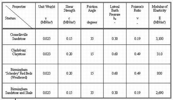
Table 1: Geotechnical Properties - Berry Street Widening.
One common procedure of simulating pre-deformations as a result of tunnel excavation within finite element calculations is to ‘soften’ or reduce the modulus of elasticity of the ground material in the excavation area. From in-situ measurements and back-calculations on other relevant tunneling projects the magnitude of modulus reduction is derived. In rock tunneling applications and in combination with the sequential excavation and support principles (NATM) used here a softening factor of 2.5 is often used to produce satisfactory results. The softening factor is applied to the in-situ modulus of elasticity Ein-situ using Enew=Ein-situ/2.5 to arrive at an appropriate relaxation of the ground and a pre-deformed opening into which the shotcrete lining is installed. Subsequently the elements within the excavation perimeter are removed and the ground loads are thereby imposed onto the shotcrete lining. This load case is then used to evaluate lining forces and design the shotcrete lining accordingly. The shotcrete lining is represented by elastic beam elements. The elastic modulus used for the so called ‘green’ shotcrete is reduced to about only 30% of its modulus when fully cured to approximate its elastic properties at the time of installation.
Figure 6: Finite Element Model for Widening within Competent Rock Section.
For tunnel widening the softening concept has been adapted to account for the existing, supported opening. Only the portion of the rock to be removed will contribute to stress relaxation within the rock mass causing loading onto the shotcrete lining. An accurate assessment is very difficult and estimates for a softening factor may only be verified in back-calculations by comparing in-situ stresses and deformations with predicted ones. A softening factor of 3.3 was found to reasonably estimate pre-deformations and lining stresses. To conservatively estimate deformations, in particular surface settlements where residential buildings were situated above the tunnel alignment at an overburden cover of some 10 meters however, no softening factors were applied and the deformations obtained by completely removing the rock mass within the excavated perimeter without the aid of support installation.
Shotcrete Lining Design for Canopy Structure Within the Mined Tunnel
A shotcrete canopy was foreseen for conditions where the distance between the rock line and the theoretical excavation line was expected to be larger than 0.5 m, otherwise this overbreak was filled with shotcrete. At large void locations rock debris typically accumulated over time on top of the brick lining. At these locations a careful excavation was done and the rubble material allowed to fall out along with the removed brick rubble. The rock face in the cavity was then supported by shotcrete and rock bolts. Subsequently a shotcrete canopy was erected and after the shotcrete gained strength it was backfilled with typically lean or fly-ash concrete pumped into the cavity. Figure 103 shows the design of the shotcrete canopy.
Because of the existence of these in parts large voids a relaxation of the rock mass due to tunnel widening in the sidewalls was not seen as an important contributing factor to the shotcrete lining design. Therefore, embedded frame analyses were carried out. The shotcrete lining was represented by two-dimensional beam elements and the subgrade reaction established by radial and tangential springs with spring constants derived from lining radii and reduced elastic moduli of the ground. The ground lining interaction was taken into account at the sidewalls but not in the crown. The future backfill with lean, ready to pump concrete mix or fly-ash was simulated as hydrostatic loading onto the shotcrete canopy.
Figure 7: Shotcrete Canopy Design.
Shotcrete Lining Design for the Mined Tunnel Section with Backfilled Voids Behind the Existing Brick Lining
Where weak rock formations were encountered in immediate vicinity of the tunnel crown after-breakage in combination with subrosion and sedimentation of fines had produced a ‘pile’ of ballast resting on the existing brick lining. This pile followed and tended to be in contact with the walls of the void opening with relatively straight sidewalls, several meters high and limited by the overlying competent strata, typically sandstones.
Similarly to the loading scenario and computational approach described above the shotcrete lining was designed using embedded frame analyses. A systematic spiling system using rebars was foreseen for the excavation and support within these sections of such backfilled voids (Figure 7). During excavation deformation of the backfill material takes place thus mobilizes internal friction of the material and also between the fill and the surrounding rock surface. Due to this mobilized arching effect between the rock sidewalls and internally within the material it was assumed that a ‘silo-effect’ (Bowles, 1982) would develop contributing to the overall self supporting capability of the ground. Based on this assumption it was concluded that the loads acting onto the shotcrete lining canopy may be reduced by a third (1/3).
Figure 8: Embedded Frame Structural Model for Tunnel Section with backfilled Voids.
Shotcrete Lining Design for the Mining Through the Section of the Existing Cut-and-Cover Structure
Approximately 160 meters of the tunnel alignment in the north were originally constructed by cut-and-cover methods, with overburden cover ranging from up to one tunnel diameter (relative to the new tunnel construction) to only about two meters. A review of soils conditions of the over 130 year old backfill material in combination with stability concerns for the side rock slopes led to a suggestion to continue mining through this backfill for a length of up to one third of the cut-and-cover section beyond the mined rock tunnel section. Due to its economy, this approach was accepted by the client and the contractor.
The calculations for this section were carried out by the finite element method to simulate a continuum and therefore incorporate the self supporting capability of the ground that could be shown within the model. The calculations showed that as for the rock sections the shotcrete lining could remain at a thickness of 150 mm with steel fiber reinforcement. To obtain conservative loading conditions for the lining design however, the removal of ground elements within the excavation line and insertion of the shotcrete lining was carried out within one step thereby imposing the entire load onto the shotcrete lining, not allowing for any pre-deformation.
Shotcrete Lining Design for the Canopy Structure Built to Replace the Previous Cut-and-Cover Tunnel Structure
The remainder of the original cut-and-cover structure was rebuilt by demolition and reconstruction by cut-and-cover methods. The most feasible approach was determined to consist of using the shotcrete canopy method. This part of the project consists of erection of lattice girders on concrete footings on 1 meter centers, attachment of two layers of welded wire fabric, one on each side of the lattice girder profile, covering of this steel lattice structure by expanded metal sheet and spraying a thickness of 250 mm of shotcrete lining. Subsequently the structure was backfilled to springline with a fly-ash concrete which was found more economical than handling and compaction of local granular materials in very confined space between canopy and very close rock side slopes. Then the shotcrete canopy was backfilled with local soils to a thickness of about 3 meters. Following waterproofing from the inside the tunnel final lining was cast in place as for the remainder of the tunnel project (Garrett, 1998).
The structural design for the shotcrete lining for this free-standing canopy structure is efficiently and appropriately carried out with embedded frame analyses. The subgrade reaction was implemented based on fly-ash elastic properties up to the springline and of initially loose and then compacted backfill materials above springline. No embedment was allowed for the upper arch from approximately ten to two o’clock locations. Compaction equipment loading and future loadings by talus materials were also incorporated for the shotcrete lining design.
Figure 9: Embedded Frame Structural Frame Model for New Cut&Cover Canopy Construction.
3. SHOTCRETE FINAL LININGS FOR TUNNELS
3.1 Shotcrete Final Lining for Tunnel Rehabilitation - Brunel Tunnel
General
The Brunel Thames Tunnel was constructed between 1825 and 1843 and was the world's first shield driven tunnel crossing under a river. The tunnel comprises of two single bores that are installed within a rectangular shape tunnel. The structural support comprises mortar bonded brickwork. The single bores are connected with brick lined arches at approximately 5.5 m centers. The inside of the tunnel was cladded with terracotta tiles mounted on dentition bricks to provide a smooth inner sight of the tunnel and protection against permeating ground and river water. After serving varying purposes for more than 150 years the tunnel required structural strengthening and waterproofing. Being partially exposed to river water and now serving as metro tunnel, a failure of the structure would have resulted in serious flooding of London's Underground system (M. Roach, 1998).
The new tunnel lining is equipped with a waterproofing system to control or exclude water ingress into the opening. The majority of the tunnel was re-lined with a cast-in-place concrete lining. Due to spacial constraints and discontinuous geometry a section at the north end of the tunnel had to be permanently supported with a shotcrete lining.
Figure 10: Typical Cross Section prior and after Rehabilitation.
Ground Conditions and Surroundings
- The general geological profile consists from top to bottom of
- Riverbed, built up of water saturated sand, gravel, silt and clay and reworked Woolwich & Reading Beds;
- Woolwich & Reading Beds (approx. 16.7m thick), a layered sedimentary system of clay, mottled clay, limestone band, pebble beds and sand; the upper part is water saturated;
- Thanet Beds (to depth) comprising very dense fine to medium sand.
Design parameters for the soil used were:
γ b Woolwich &Reading Beds = 19.0 - 22.0 kN/m3
E Woolwich &Reading Beds (River Bed) = 25.0 MNm2
E Woolwich &Reading Beds (Clay) = 50.0 MNm2
E Woolwich &Reading Beds (Limest.Band) = 500.0 MNm2
E Woolwich &Reading Beds (Pebble Beds, Sands) = 75.0 MNm2
E Thanet Sands = 100.0 MNm2
c’ Woolwich &Reading Beds, Thanet Sands = 0 - 10 kN/m2
Φ’ Woolwich &Reading Beds (Clay, Riverbed) = 23 - 25°
Φ’ Woolwich &Reading Beds (Limest.Band) = 40°
Φ’ Woolwich &Reading Beds (Sands, Pebble Beds) = 30 - 35°
Φ’ Thanet Sands = 40°
where:
γ = bulk density
E = Modulus of elasticity
c’ = Effective cohesion
Φ’ = Effective friction
The mortar bonded, structural brickwork of the existing structure was capable of sustaining the groundwater and ground loads at the time of lining installation. The thickness of the structural brickwork varies strongly. The prevailing thickness is in the range of 400 to 600 mm.
Each single bore to be relined is approximately 4.2 m wide and 5.0 m high.
Soil cover (river bed) above the tunnel varies between 0 and approximately 3 m beneath the river Thames increasing up to approximately 20 m at the tunnel’s ends.
Design Requirements
The following requirements had to be met by the new lining:
• Replication of various existing architectural features including pilasters, capitols, arches and longitudinal as well as circumferential banding.
• The support provided by the existing structural brick lining was to be ignored for the lining design. It had to be assumed that the brick lining will deteriorate to granular material.
• The new lining had to withstand the full hydrostatic head being equivalent to high tide level of the river Thames.
Design Approach
For the brick structure, the assumed design parameters were:
E(current brickwork) = 15,000.0 MN/m2
Eh (degraded brickwork) = 150.0 MN/m2
γb current°raded = 21.0 kN/m3
For the new shotcrete lining, the assumed paramters were:
fcu = 60 N/mm2
lining thickness typically 200 mm
where:
γ = specific weight
E = Modulus of elasticity
f cu = ultimate design strength
During the design process, it was assumed that the brick structure in place would have sufficient strength to support the existing ground and groundwater loads at the time of lining installation and concrete setting. Therefore, no particular requirements regarding to early shotcrete strength had to be met by the shotcrete mix. The shotcrete lining was designed to carry full ground and hydrostatic loads on the long term, based on the assumption that the structural brick lining will degrade to granular material. This granular material would not provide positive ground support but subgrade reaction exceeding that of the surrounding natural soil in some future.
A sensitivity analysis using lateral earth pressure coefficients varying between 0.5 and 2.0 was carried out resulting in seven load cases to be analyzed. The most onerous loading conditions resulting from the load case using a lateral earth pressure coefficient of 2.0 were used for the design. The biggest effect by changes of the lateral earth pressure were identified in the rather strait sidewalls.
In order to provide an overview over the reaction of the structural brickwork on brick removal and complex stress re-distribution processes at the cross passages (arches) and a calibrating tool for the two-dimensional analyses, a three-dimensional Finite Element analysis of the brick structure was carried out at an initial stage of the project. Following that, a series of two-dimensional calculation cross sections were analyzed using a Finite Element program to assess the loading condition, section forces and bending moments in the new lining for the short and long term stage.
The forces and bending moments derived from the Finite Element analyses were then checked using simple numeric hand calculations and used for the design calculations for the lining. The new lining was designed to Serviceability Limit State and Ultimate Limit State in accordance with BS 8110.
Though the waterproofing system is perforated at the current stage and intruding groundwater can drain freely, provisions were made to grout and fully seal the structure at a later stage, if groundwater ingress reaches unacceptable levels due to future brick deterioration. Thus, the new lining had to be designed to withstand full hydrostatic loads.
In order to improve the early thermal shrinkage control and to achieve increased impact strength the shotcrete was reinforced with steel fibers in addition to the conventional rebar structural reinforcement.
Installation of the Lining
After removal of all services, tracks, ballast and drainage piping, the terracotta lining and dentition bricks were removed to gain space for the new lining and clearance requirements. Following that, the new combined concrete invert and track slab was installed.
At locations where structural brickwork had to be removed to obtain additional space, temporary steel support was utilized. Each widened section was immediately re-lined after treatment before the temporary support was removed.
The shotcrete lining was sprayed against a membrane waterproofing and back of lining drainage system in sections of 3 m length.
The architectural features were installed by spraying mortar into pre-installed forms onto the finished tunnel surface.
3.2 Shotcrete Final Lining for Ventilation Tunnels - London Bridge Underground Station
General
As described above, the new London Bridge Underground Station formed a complex underground scheme. Due to geometrical and contractual constraints, the ventilation tunnels had to be built following a complicated alignment with multiple horizontal and vertical bends. Horizontal curve radii ranged between approximately 12 and 25 m and the vertical curve radii ranged between 10 and 22 m.
The complicated alignment of the ventilation tunnels required a flexible lining method that allowed an economic installation of a watertight and durable final lining. Furthermore, the ventilation tunnels accommodate two completely separated airducts. Separation is provided by splitter slabs.
Ground Conditions and Surroundings
The London Bridge Underground Station is located in the center of London beneath historic and new surface structures. These structures are founded on shallow foundations as well as on pile foundations that reach into the London Clay.
All ventilation tunnels are situated in London Clay with an approximate ground cover above tunnel roof ranging between 16 and 21 m. Clay cover above the tunnel roof varies between approximately 6 and 11 m, groundwater head above tunnel roof ranges between approximately 9 and 14 m. The schematic geological profile shown above applies.
Soil parameters used were:
γb Made Ground = 17 kN/m3
γb Gravels = 20 kN/m3
γb London Clay = 19.5 kN/m3
E London Clay = 95.0 MN/m2
υ Lonodn Clay = 0.3
cu London Clay = 180 kN/m2
Φ London Clay = 0°
where:
γb = bulk density buoyant
E = Modulus of elasticity
υ = Poisson’s Ratio
cu = Undrained cohesion
Φ = Undrained friction
Coefficient of lateral Earth Pressure in London Clay
k = 1.0
Design Approach
For the assessment of long term loadings, it was required to assume full overburden load acting upon the permanent tunnel lining. The initial shotcrete lining was considered deteriorated (with the exception of one load case) and no support would be provided by the initial shotcrete lining on the long term.
Design parameters for the shotcrete lining:
fcu = 40 kN/m2
E = 14,000.00 MN/m2
Material Factors shotcrete:
γculs = 1.5
γssls = 1.0
γcls = 1.0
Material Factors steel reinforcement:
fy = 460 kN/m2
E = 210,000.00 MN/m2
γsuls = 1.15
γssls = 1.0
Minimum cover to steel
d = 0.045 m
Load Factors for ground loads:
γluls = 1.4
γlsls = 1.0
where:
γculs = concrete Ultimate Limit State
γcsls = concrete Serviceability Limit State
γssls = steel Serviceability Limit State
γsuls = steel Ultimate Limit State
Surcharge load by existing surface structures:
PS = 0.060 MPa
Section forces were analyzed for Ultimate Limit State (ULS) and Serviceability Limit State (SLS) condition. Using a subgrade reaction model, where the shotcrete lining is modeled by beam elements and the subgrade reaction of the ground by a series of linear, radial and tangential springs, 4 load cases were analyzed.
The first load case analyzed the ULS condition under full overburden ground and hydrostatic load, while the second load case dealt with ULS load factors for the bending moments and with SLS factors for the corresponding normal forces. This results in the worst possible combination of the ultimate bending moment with less section normal forces than derived in load case 2.
Load case three was carried out to check the flotation of the lining under hydrostatic load using SLS factors, assuming the shotcrete lining still supports the ground loads. This load case was carried out to assess the normal force and bending moment combination under unfavorable conditions of low normal forces due to the absence of ground loads and high bending moments due to restrained flotation.
Load case 4 formed a brief assessment to check the performance of steel fiber reinforced shotcrete in relation to cracking resistance and durability of the shotcrete lining.
Design Requirements
For the long term, full overburden load and surcharge loads from the surface buildings had to be taken into account.
A permanent groundwater drainage during the tunnel operation water leakage into the tunnel system was neither acceptable for the maintenance and operation reasons nor for long term ground settlement reasons. Thus, the permanent shotcrete lining of the ventilation tunnels had to be water tight under the full hydrostatic head of approximately 14 m.
Since the ventilation tunnels are not part of the public station area, the smoothness of the inner lining surface had to be sufficient to avoid unacceptable airflow resistance and turbulence, rather than to meet architectural finish criteria. However, the final product achieved could be used for public station areas where some architectural cladding is applied.
Installation of the Lining
The shotcrete lining was sprayed against a separation membrane that was fixed onto the shotcrete initial lining. Dependent on the tunnel geometry the lining was installed in section lengths of minimum 2.5 m. Immediately after each section sprayed, an unreinforced finishing layer was applied on top of the steel fiber reinforced shotcrete shell and trowel finished. Joints between the section were specially formed by templates to maintain tight contact and sufficient water tightness.
4. CONCLUSION
The above case histories show the great variety of shotcrete lining applications in the tunneling industry. They also demonstrate that shotcrete initial lining design is inseparably coupled with the design of an appropriate excavation and support sequence. Design experience, full appreciation of the ground conditions and ground behavior as well as ground - structure interaction form the basis for the design of a shotcrete lining, regardless whether the shotcrete lining will serve for initial or long term support.
A practical construction concept, skillful implementation of the design concept on site paired with good quality management and adequate shotcreting equipment lead to the success at the construction site.
REFERENCES
Baratt, D., O’Reilly, M., Temporal, J., 1994: ‘Long-term measurements of loads on tunnel linings in
overconsolidated clay’, Proceedings, Tunnel 1994, p. 469 - 481, London, UK, 1994.
Bieniawski, Z.T., 1978: ‘Determining Rock Mass Deformability - Experience from Case
Histories,’ J. Rock Mech. Min. Sci. 15.
Bowles, J. E., 1982: ‘Foundation Analysis and Design,’ Third Edition, McGraw Hill Book
Company, New York.
Garrett, R., 1998: ‘The Austrian Way’, International Construction, March Issue.
Gall, V., Zeidler, K., Predis, T. and J. Walter, 1998: ‘Rehabilitation concepts for brick lined
tunnels in urban areas,' Proceedings, World Tunnel Congress ‘98 “Tunnels and Metropolises”, Sao Paulo, Brazil, April 25 - 30.
Groves, P., Morgan, S., 1997: ‘Engineering consequences of ground conditions on NATM works at London
Bridge Station, Jubilee Line Extension’, Proceedings, Tunnel 1997, p. 677 - 692, London, UK, 1997.
Roach, M., 1998: ‘The strengthening of Brunel’s Thames Tunnel’, Proc.Instn.Civ.Engrs Transp., 1998, 129,
p. 106 - 115, Paper 11628, London, UK, 1998
Zeidler, K., Groves, P., Sharrocks, D., Allen, R.: ‘Surface Settlement due to the construction of the London
Bridge station tunnels by NATM’, Proceedings, World Tunnel Congress ‘97, “Tunnels for People”, p. 429 - 434, Vienna, Austria, April 12-17, 1997
Zeidler, K. & Gall, V., 1997: ‘London Bridge Sation, Jubilee Line Extension’, Proceedings, RETC 1997,
Chapter 39, p. 631 - 654, Las Vegas, USA, April 1997.
Zeidler, K., 1998: ‘About the influence of compensation grouting on shotcrete tunnel linings at London Bridge
Station, UK’,Proceedings, World Tunnel Congress ‘98 “Tunnels and Metropolises”, p. 1059 - 1064, Sao Paulo, Brazil, April 25 - 30, 1998.