You are here
Rehabilitation concepts for brick lined tunnels in urban areas
April 25, 1998
Sao Paulo, Brazil
Rehabilitation concepts for brick lined tunnels in urban areas
World Tunneling Congress '98
Proceedings of the World Tunneling Congress 1998 on Tunnels and Metropolises, Sao Paulo,Brazil, 25-30 April 1998
ABSTRACT
Many old tunnel structures exhibit conditions characterized by deterioration of the tunnel linings. This occurs usually in connection with water infiltration being the main factor and causes conditions not tolerable for the intended tunnel use and therefore operator and owner. Other circumstances that especially in recent years call for a refurbishment of old tunnel structures include the need for enhancing the current use or accommodating different transportation needs. Using two case histories as a basis, rehabilitation concepts using NATM technology for brick lined tunnels in urban areas are introduced. The first case history is the over 130-year-old Berry Street Tunnel in Pittsburgh, Pennsylvania, USA, which was widened to adapt to PAT's (Port Authority of Allegheny County) new bus-way connection between downtown Pittsburgh and the new, international airport. The second is the refurbishment of the world's first shield-driven tunnel under a river constructed by Marc Isambard Brunel in London, UK, between 1825 and 1843. The refurbishment here was primarily for lining strengthening while incorporating new clearance requirements by LUL (London Underground Limited) vehicles.
1. BERRY STREET TUNNEL WIDENING
1.1 Background
The rubble-masonry and brick lined Berry Street Tunnel was initially constructed for the Pittsburgh, Cincinnati & St. Louis Railway. An original tunnel was built in 1865 (then called the Cork Run Tunnel) as a 4 m wide, single track rail tunnel. It was widened in 1873 to approximately 8 m, double track with a 65 cm thick brick-lined horseshoe tunnel. Throughout its existence the tunnel has been frequently repaired for structural reasons of spalling brick layers and was finally abandoned and closed in the early 1960's.
More than thirty years later the Port Authority of Allegheny County in Pittsburgh, PA saw benefits in using the former railroad alignment and right-of-way to accommodate its new busway connection between downtown Pittsburgh and the new Pittsburgh International Airport. Under this scheme it was envisioned that the tunnel is widened from the old about 8 meter springline diameter horseshoe tunnel beyond its circumference to a ca. 12 m diameter twolane busway tunnel. The finished tunnel product was designed according to state-of-the-art tunnel technology including a flexible, plastic waterproofing membrane, final cast-in-place concrete lining and a jet fan based longitudinal system for tunnel ventilation.
The total tunnel length is 870 m of which 710m involve mined tunneling for the refurbishment work whereas the remainder of 160 m included the refurbishment of a cut-and-cover tunnel section. Mined tunneling in particular close to the southwest portal called for excavation and support beneath sensitive surface and subsurface structures with mainly single home residential buildings located above the tunnel centerline with a separation cover of some 10 m.
1.2 Tunnel Conditions
Determination of the tunnel's stability involves assessment of tunnel lining conditions in combination with those of the ground surrounding the opening. Various methods lead to a satisfactory assessment of brick lining conditions and include among others visual inspection and systematic core drilling. Stress conditions in brick linings, if required for the rehabilitation task are assessed using in-situ tests based on relaxation (i.e. Doorstopper method) or compensation (i.e. flat jack) principles (Froehlich, 1996). Determination of the ground conditions behind the tunnel lining however, may pose challenges. Not only in prescribing an exploration program but also to provide accurate interpretation of the findings such as boring samples becomes more difficult since the ground had already been mined once before. Interpretation of samples in tunnel vicinity therefore has to concentrate not only on the description of the base ground material but has also to recognize how the ground behind the lining has been reworked over time. Records such as shown in Figure 1 are often of limited help only since they tend to be idealistic and lack the effect of time where the elements deteriorated rock and support elements to varying degree.
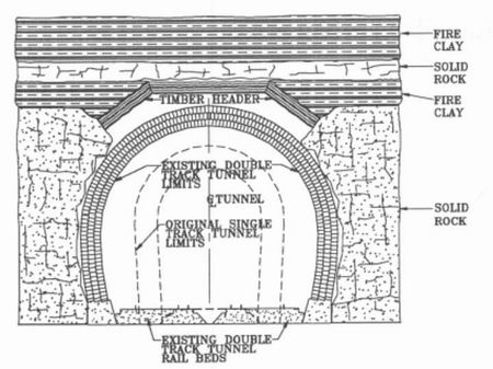
Figure 1. Reproduction of plate II - Cross section of Cork Run Tunnel (Becker, 1876).
1.2.1 Causes of damage
Excavation and support techniques used in rock tunneling decades ago tended to promote loosening of the surrounding ground; mainly due to late support installation and lack of close contact between ground and support. Depending on rock type such as in generally weak, sedimentary rock layers this often left larger areas around the needed lining clearance often severally fractured, with various degree of separation between the rock strata. Although backpacking, which involves filling between the tunnel lining and overbreak contour has been occasionally attempted, it was not as accurately and carefully done as to assure a proper, long-term contact between lining and rock. Over time water infiltration resulted in subrosion and weathering effects. Afterbreaking of unsupported strata either from the beginning or after timber supports had rotted away led to piling up of rock rubble on the lining. Occasionally sedimentation of fines caused filling of the rock rubble voids to varying degree creating a conglomerate difficult to assess by exploration and difficult to predict by behavior.
In competent rock formations on the contrary, overbreak areas, if present, might have been left unfilled and the rock shape, along with the cavity behind the lining may still exist almost unchanged except some spalling effects that left broken rock material lying on top of the brick lining.
Throughout the life of the tunnel the brick linings have been influenced by water infiltrating through the surrounding ground leading to washout effects of the brick mortar. Condensation waters from the tunnel's inside, weathering and most importantly the impact of freeze thaw cycles during cold winter months led to deterioration of the linings, loss of strength and spalling effects (Spang, 1971 and Grueter et. al., 1996).
For the widening of the Berry Street tunnel the ground conditions behind the tunnel lining were of primary concern. The integrity of the brick lining played a secondary role in planning the reconstruction work. Its stability was desirable to support the opening while reconstruction activities were ongoing, such as for safe hauling of muck and other logistics.
1.2.2 Conditions
The stratification along the tunnel alignment which includes claystone, siltstone, sandstone, coal layers and shale is shown in Figure 2a. Based on an extensive exploration program carried out for the design different zones of ground deterioration have been identified along the tunnel alignment. Figure 2b shows a series of graph plots above the brick lining which indicate brick lining thickness, presence of ground material above it and void space.
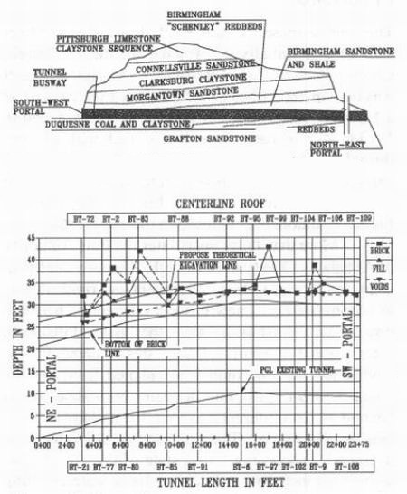
Figure 2a. Berry Street Tunnel geologic section. Figure 2b. Alignment Study.
1.3 Bid Design Reconstruction Approach
The tunnel reconstruction approach initially developed by the Port Authority's engineers was based on the premise that the deteriorated ground above and around the existing tunnel lining be improved prior to start of any reconstruction procedure. According to this approach the ground above the tunnel opening would be improved by first drilling a designated pattern of grout injection holes into the tunnel crown and sides. A systematic grouting program using cementitious grout was foreseen to fill as many voids behind the brick lining as possible. It was also to fill rock delamination and fissures present up to a depth of some 7 m. After the grouting operation it was foreseen to install a dense pattern of rock bolts driven into the rock through the existing brick lining. The rock bolt length was also 7 m and the spacing of the rock bolt pattern ranging between 1 and 1.5 m cc. Following the ground improvement the tunnel widening was designed using a 25 cm thick shotcrete lining as initial tunnel support with lattice girders at 1 to 1.3 m distances depending on location. To presupport the grouted ground, a systematic rebar spiling was dictated by the contract documents. This design was viewed by the Port Authority as a reconstruction approach complying with the standard criteria: high safety standards during construction, extensive overbreak containment, and conservative structural integrity standards.
1.4 Value Engineering Approach using the NATM
Following award of the tunnel widening contract in late 1995 Mosites Construction Company (MCC) of Pittsburgh, Pennsylvania proposed to the Port Authority a value engineering (VE) on the tunnel refurbishment. Developed by MCC's subcontractor Dr. G. Sauer Corporation (DSC) the redesign was based on three main premises:
1. Elevate the tunnel alignment by up to 1.5 m (see Figure 2b).
2. Develop a ground support classification system and adjust support as required by ground conditions encountered in the field.
3. Introduce a 'rounded' cross section as opposed to the bid design's horseshoe geometry with straight side walls.
By the first assumption the future tunnel crown was elevated into ground conditions that were generally less deteriorated based on review of the exploratory boring results. Therefore, the amount of support, i.e. rock bolts and shotcrete lining thickness could be reduced. The second premise bears multiple thoughts. First, to determine the actual ground conditions in the field the grouting program would be eliminated. Secondly, the excavation would be done by opening rounds of very limited length, depending on ground conditions between 1 and maximum 2.5 m. This, in connection with the existing exploration program would allow for a detailed assessment of in situ conditions and installation of support means as dictated by the ground, resulting in a more economic tunnel reconstruction. The third premise of the VE concept which may not be separated from the other two also allowed for the reduction of both shotcrete and concrete lining thicknesses. Compared to the 25 cm thick bid design shotcrete lining the VE shotcrete uses only 15 cm. The final concrete lining was reduced from a 38 cm thick reinforced cast-in-place concrete lining to a 30 cm unreinforced concrete liner. As was later shown in a series of finite element structural computations the elimination of straight side walls facilitated reduction of bending moments in the curved lining. A cross section combining the proposed VE geometry and old tunnel structure is displayed in Figure 3.
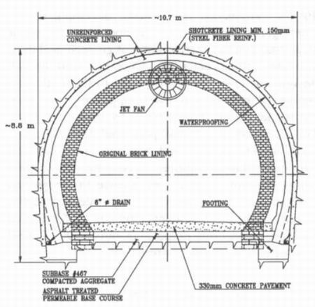
Figure 3. Typical cross section of old and reconstructed Berry Street Tunnel.
Using the VE proposal thus eliminating grouting (200,000 bags of cement) and over 10,000 rock bolts while reducing lining thicknesses cost savings of about US$ 2 million could be realized. According to the value engineering clause the cost savings are split equally between the owner and the contractor.
Following detailed review of the VE proposal PAT's engineers suggested development of contingency measures, i.e. support types for worse than (based on the interpretation of geotechnical data) expected ground behavior. Once provided, the VE design was technically acceptable to the Authority. Before bid the contractor had been pre-qualified to do the tunnel refurbishment work by taking on board DSC's experienced tunnel personnel utilized in key positions including tunnel superintendent, foremen and geotechnical engineer. Assuring construction safety through combined experience in design and construction, while providing equivalent or better features of the finished tunnel structure PAT accepted the value engineering proposal in early 1996. Tunnel reconstruction started in April 1996.
1.5 VE Design and Construction
A ground behavior classification along with definition of support types was established. Along with contingency support types the following classes were incorporated in the design:
SW (south west) Portal: Minor after break and shallow cover above the tunnel crown; systematic rebar spiling, lattice girders on 1 m centers, 1.2 m round length in top heading and 2.4 m in the bench. For the case of a contingency support the spiling would be converted into grouted pipe spiling. The excavation and support at the SW portal was the most conservative one not only due to shallow cover and the deteriorated claystone in the tunnel crown but also because residential buildings were located directly above the tunnel alignment with tight settlement restrictions. Figure 4 shows typical excavation and support for this support type.
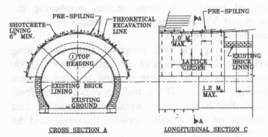
Figure 4. Excavation and support at SW portal.
Class I: Stable ground with minor after break decreasing significantly with time. Rebar spiling as required, pattern rock bolting, lattice girders as required, maximum round length 2.5 m in top heading, 5 m in bench. Contingency type A: fairly stable ground with minor to moderate after break. In these conditions lattice girders would be installed every 1.5 m and excavation lengths reduced to 1.8 m in top heading and 3.6 m in the bench. Contingency type B: blocky ground with voids above the brick liner. Significant after break and overbreak. In these conditions systematic rebar spiling would be added to the excavation and support per contingency type A. Conditions and reconstruction according to contingency type B are displayed in Figure 5.
Class II: Stable blocky ground with significant voids over the brick liner, minor after break and overbreak. Rebar spiling as required, pattern rock bolt installation, lattice girder as required, maximum round length 2.5 m in the top heading and 5 m in the bench. A shotcrete canopy built under large voids and before backfilling. Contingency type D: blocky ground with large voids over the brick liner and significant after break and overbreak. Systematic rebar spiling, pattern rock bolt installation, lattice girders on 1.5 m to 2.5 m centers and round lengths at maximum of 2.5 m in the top heading and 2.5 m in the bench.
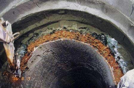
Figure 5. Excavation and support in contigency type B.
A shotcrete canopy was generally built where the distance between the rock line and the theoretical excavation line was larger than 0.5 m, otherwise this overbreak was filled with shotcrete. At large void locations rock debris typically accumulated over time on top of the brick lining. At these locations a careful excavation was done and the rubble material allowed to fall out along with the removed brick rubble. The rock face in the cavity was then supported by shotcrete and rock bolts. Subsequently a shotcrete canopy was erected and after the shotcrete gained strength backfilled with typically lean or fly-ash concrete pumped into the cavity. Expectedly (see large void areas in Figure 2b) these locations occurred in the vicinity of the north east portal. Figure 6a shows the design of the shotcrete canopy and Figure 6b shows its installation during reconstruction.
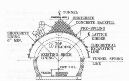
Figure 6a. Shotcrete canopy design.
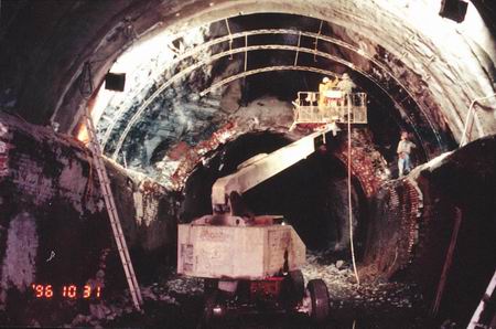
Figure 6b. Canopy installation.
Productivity during tunnel reconstruction was acceptable to the contractor. After a learning curve tunneling progressed from up to three headings, one from each portal and one started within the tunnel averaging 4.6 m per 24 hour day. Following waterproofing (see Figure 7) the concrete lining work was completed in August 1997.
2. REFURBISHMENT OF BRUNEL'S THAMES TUNNEL
2.1 Background
The Thames Tunnel being the world's first shield driven tunnel crossing under a river was constructed by Marc Brunel between 1825 and 1843. The approximately 400m long structure connects Wapping Station on the north bank with Rotherhithe Station on the south bank of the River Thames in east London. Originally designed for horse and foot traffic, the tunnel now forms part of London Underground Limited's (LUL) system.
The brick tunnel structure has a rectangular outer profile and twin side-by-side horseshoe inner tunnel profiles. Brick lined arches at approximately 5.5 meter centers connect both tubes. The arches were cut out of the inner wall separating the two bores after the tunnel had been completed.
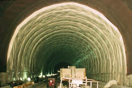
Figure 7. Berry Street Tunnel waterproofing.
The structure is located at very shallow depth below the bed of the River Thames over much of its length and is situated mostly in the alluvial deposits and strata of the Woolwich and Reading Beds. The river sediments are fully water saturated and liquified at places.
The shield comprised twelve vertical side-byside cast-iron frames, each with three compartments. Each frame was advanced separately by the use of screw jacks acting against the mortared brickwork lining which was built close behind the shield. Inside, the twin bores were lined with Terracotta tiles which were fixed generally on 'dentition' brickwork protruding from the structural brick lining.
Refurbishment primarily aimed for strengthening of the tunnel support lining and the twin bores should meet the clearance requirements of LUL's modern vehicles including the clearances for the dynamic envelope of the carriages and the services to be contained within the tunnel.
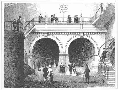
Figure 8. Historic View of the Thames Tunnel.
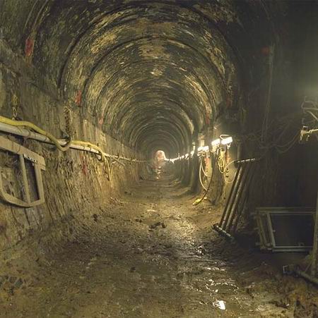
Figure 9. Tunnel before rehabilitation.
2.2 Tunnel Conditions
The inner profile of the structural brick to the bores was irregular. Terracotta tiling was fixed at the dentition brickwork producing a relatively uniform, smooth internal profile circumferentially and longitudinally. Groundwater leaking through the structural brickwork was collected between the dentitions and lead behind the cladding to invert level. In some places, due to misalignment of the structural brick profile, tiles were fixed directly onto the structural brick and drainage grooves were 'chased' into the structural brick to maintain the capability of containing any leakage into the tunnels. Water seepage ran down to dip sumps located near the lowest point in the tunnels from where it was pumped to the surface.
Continuous water inflow and train operation affected the structural brickwork and particularly the internal cladding of the tunnels. Numerous small diameter core drillings penetrating the cladding and structural brickwork were performed to gain information on the thickness of the cladding and the conditions of the structural brickwork behind it. The investigation revealed varying levels of brick and mortar quality, such that provisions for a wide range of refurbishment scenarios had to be designed.
2.3 Contractual Aspects
The Dr Sauer Company (DSC) was originally commissioned by LUL to undertake the design of the refurbishment method and the new lining to the twin bores. The commission was subsequently novated to Taylor Woodrow Civil Engineering Ltd (TWCE) when they were appointed main contractor for the works.
In April 1995, the structure gained Grade II Listed status (historic structure) and it then became a requirement that the four cross passages at the southern (Rotherhithe) end of the alignment and the two bores with their tiled finish over this length be retained in their current condition as a 'Preserved Section'. Also, all arches between the bores, which had been intended to be infilled with structural blockwork, had to remain open.
Consequently, all arches and both bores had to be equipped with an internal lining reflecting the historic architectural features. A back-of-lining drainage system had to be incorporated.
2.4 Design Requirements
Although the broad principles to be adopted for the design of the tunnel linings were available, specific requirements arising from the 'Listed' nature of the structure had to be addressed. The refurbishment procedures finally adopted were only resolved during the design process through a 'Design Panel' comprising representatives from LUL, TWCE and DSC. Much of the tiling to the tunnels was still in place and obstructed visual inspection of the structural brickwork. This resulted in very limited availability of reliable information on structural brickwork.
The design objectives were to minimize the permanent tunnel lining thickness to accommodate the required structure gauge envelope while aiming at the same time to restrict the removal or trimming of structural brickwork. The target minimum thickness of remaining brickwork was 675mm whereas the target minimum thickness of lining was 200mm. The lining had to be constructed from a minimum 40 N/mmý concrete with conventional steel bar and steel fibre reinforcement. The invert to the lining and the track slab for the rails were designed as a composite structure to minimize lining thickness and brickwork removal in the invert.
At both ends of the bores the new alignment had to match with the existing track alignment to meet the alignment requirements for the subsequent operation of stations and metro lines.
The lining is required to withstand the full loading imposed by the soil (including the existing brick fining which was not considered to contribute to the support on the long term), surface structures, permanent way structures, services and the full hydrostatic loading generated by groundwater and the river at its maximum tidal level. Structural analysis of the tunnel lining was carried out using 2- and 3-dimensional Finite Element methods.
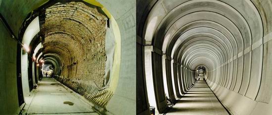
Figure 10. Tunnel under refurbishment and fully refurbished tunnel.
2.5 The Lining
The design ultimately involved 200mm thick concrete linings for both the tunnel bores and the cross passages, reinforced with two layers of welded wire fabric and incorporating steel fibres. The steel fibres were not considered to contribute to the structural capacity of the linings but they were acknowledged in respect of their beneficial influence on early thermal cracking and impact resistance.
A waterproof membrane with a geotextile fleece around the periphery of the tunnels above invert level was installed between the permanent lining and the existing structural brickwork. A 'back-of-lining' drainage system which allows any seepage from the brickwork to be collected in stripes of drainage mats behind the waterproofing system enhances the drainage system. The water collected in the 'back-oflining' drainage is lead through weep perforations in the lining into half-round drains formed in the track slab.
2.6 The Construction
The refurbishment operation followed the following steps:
-
preparation for and construction of track slab;
-
preparation for and lining of arches;
-
preparation for and lining of both bores.
In preparation for the lining of the respective parts of the Thames Tunnel, brickwork was trimmed back as required, smoothening layers (patches) applied, and the back-of-lining drainage as well as the waterproofing system installed. TWCE constructed the inner linings to the tunnel bores and the cross passages using cast in place concrete applied behind specially fabricated steel shutters. The steel shutters were designed so that main tunnel linings was in modular form such that it could be shortened as necessary in areas where significant amounts of structural brickwork had to be removed to limit the length of tunnel so affected. Sprayed concrete was used to form the linings to the two bores at the northern (Wapping) end of the alignment over a length of approximately 18m because of the complex geometry resulting from the fact that the tunnel was on a horizontal transition curve and the requirement to tie-in with the existing portal structure.
Monitoring in the main tunnels during brickwork removal included tape convergence measurements and load and deformation measurements using temporary steel frames. The frames, which were jacked against the brickwork, were fitted with load cells and strain gauges which were continuously monitored through a computer controlled system.
Construction was successfully completed in the Spring of 1997. DSC seconded experienced site personnel to TWCE to form an integrated part of the site team. The DSC site staff also formed the interface between the site and the design team at the home office to ensure a safe and skillful implementation of the design.
3. SUMMARY AND CONCLUSION
The refurbishment of two brick lined tunnels in urban settings has been presented. The over 130 year old Berry Street rock tunnel was widened to accommodate different transportation needs. Brunel's tunnel, over 150 years old being the first shield tunnel beneath a river constructed in soft ground, required lining strengthening while accommodating new clearance envelopes for vehicles. Using the observational character and support / pre-support elements of the NATM it has been shown that exposing the ground allows for a justified installation of support according to support needs. Qualified application enables an economic and safe tunneling. By adjusting to minimum traffic requirements and other schedule restrictions the reconstruction concepts presented are equally applicable to refurbishment of tunnels which need to remain operational.
Similar to the Berry Street Tunnel (Pittsburgh), detailed investigation during the reconstruction period at the Brunel Tunnel provided an increasing level of knowledge on the brick work conditions, and consequently adjustments or amendments to the design have been carried out.
Acknowledgment: The authors are grateful for the support provided by LUL by releasing the photographs shown in this article for publication.
REFERENCES
Becker, M. J. 1876. Reconstruction and Enlargement of Cork Run Tunnel on the Pittsburgh, Cincinnati & St. Louis Railway, Transactions, American Society of Civil Engineers, Inc.
Froehlich, B, 1996. Belastung alter Tunnel: Schadensbilder - Untersuchungen - Interpretationen, Geotechnik (1996) Nr. 3.
Garrett, R. 1997. Pittsburgh Berry Street Rebuild, North American Tunneling, June 1997 Issue.
Grueter, R. & W. Schuck, 1996. Sanierung alter Tunnel der Deutsche Bahn AG, Geotechnik (1996) Nr. 3.
Spang, J. 1971. Design, Construction and Maintenance of Tunnels of German State Railways, Tunnels & Tunnelling, September 1971.