You are here
About the influence of compensation grouting on shotcrete tunnel linings at London Bridge Station
About the influence of compensation grouting on shotcrete tunnel linings at London Bridge Station
World Tunnel Congress 1998
Proceedings of the World Tunnel Congress '98 in Tunnels and Metropolises
Sao Pailo, Brazil, 25-30 April 1998
ABSTRACT
During the construction works for the new Jubilee Line London Bridge Station (UK) extensive Compensation Grouting was carried out to protect sensitive surface buildings. Trial grouting was carried out and a sophisticated control system employed. The extensive recording and monitoring system allowed the collection of important data to assess the influence of Compensation Grouting on the shotcrete tunnel linings of the Pilot Tunnel and station tunnels. Initial results of a monitoring data review are given.
1 GENERAL
Major tunneling projects in urban areas increasingly require the application of settlement limiting construction methods combined with additional measures to limit the effect of settlements. Compensation Grouting has been employed for limitation of surface settlements for many years. By fracturing the soil and forcing the grout material into the ground, soil is displaced, and volume loss and settlements compensated. During the construction of the new Jubilee Line London Bridge Station, the most complex underground station construction of the Jubilee Line Extension Project in London, UK, an extensive Compensation Grouting system was developed to protect sensitive, historic surface buildings located in the area influenced by the tunneling activities. A highly sophisticated control and pumping system was installed to ensure the control of injection, displacement and surface heave. This system also assisted to limit the influence of Compensation Grouting on the support of various tunnels in vicinity of the treated area that were previously built or under construction.
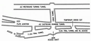
The majority of the station tunnels was built following the principles of the New Austrian Tunneling Method (NATM) using shotcrete as initial support. Before the actual construction of the London Bridge Station commenced, Trial Tunnels were constructed to simulate the situations expected for the construction of the running and station tunnels. Above the wide span Trial Tunnel (11.3 m) intensive grouting tests have been carried out to assess the effect of Compensation Grouting on the surface heave and the tunnel lining.
Figure 1. General Arrangement of the Trial Tunnels.
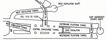
Figure 1. General Arrangement of the Station Tunnels.
The NATM tunneling was carried out mainly in London Clay, an over-consolidated, randomly fissured, tertiary clay. Clay cover above the station tunnels is approximately 12 - 16 m, whereas Compensation Grouting was carried out approximately 6 m below the clay surface, typically Compensation Grouting was carried out approximately 6 m below the clay surface, typically 19 m below ground surface. Fracture grouting was carried out through tube-a-manchette (rubber sleeve pipes). The grouting openings and rubber sleeves were arranged in 0.5 m spacings along the tube-a-manchette.
Currently a series of investigations are under way as to the effect of Compensation Grouting. This factual paper reports on the effects of Compensation Grouting on shotcrete tunnel linings and the ground observed at selected tunnel sections of the new London Bridge Station Project. Further investigation of the data collected will be carried out, the theoretical background of the ground and lining behavior clarified and models developed in the future.
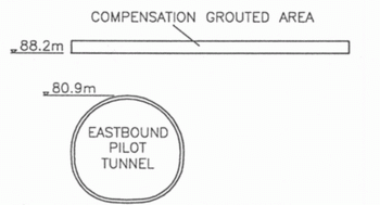
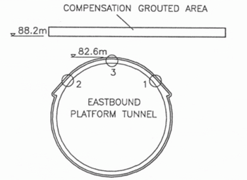
Figure 3. Schematic Section through the eastbound
Platform Pilot Tunnel at Station 1215.
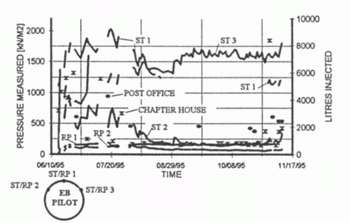
Figure 4. Pressure vs Time over five month period.
2 MONITORING
2.1 Monitoring
Monitoring is an integrate part of NATM tunneling. Accordingly, various tunnel sections were equipped to monitor the ground and lining response to mining. Additional monitoring sections have been arranged to monitor the effect of Compensation Grouting on the ground and the tunnel lining. In order to measure the lining deflections, arrays of convergence pins were arranged in sections. Readings were carried out by using precise theodolites to detect the absolute movements. However, the results from convergence monitoring were not considered they do not provide additional information for the purpose of this paper. The ground loads acting upon and the stress acting within the tunnel lining were measured by using pressure cells. These were tangentially arranged between the lining and the ground for measuring the ground loads and radially within the shotcrete section for lining stress measurement. Readings were taken several times a day and subsequently processed to be interpreted. Generally, real time readings were taken. In an area remote from the station area an array of Piezometers was installed to measure changes of porewater pressure during trial Compensation Grouting passes. The area tested was considered not to be influenced by the tunneling activities. The Piezometers were arranged in arrays around the grouted sleeve pipe .
2.2 Selection of Monitoring Sections and Readings
To provide a representative picture reading results of three monitoring sections were selected to be highlighted in this paper. To provide a variety of reading results data collected at the eastbound Platform Pilot Tunnel (approximately 5.3 m tunnel width) and two wide span tunnels (eastbound Platform Tunnel, 9 m span and Trial Tunnel, 11.3 m span) were selected. For comparison reasons, information on the readings of porewater pressure measurements is given as well.
3 OBSERVATIONS AT EASTBOUND PLATFORM PILOT TUNNEL, Sta. 1215
3.1 Situation
Prior to the construction of the eastbound Platform Tunnel an approximately 5.3 m wide Pilot Tunnel was built. This tunnel was located in the lower part of the proposed Platform Tunnel with its invert slightly below the Platform Tunnel invert level.
The selected monitoring cross section was located at Station 1215 adjacent to the proposed most westerly passenger cross passage. Two sensitive surface structures are located above this tunnel section: The `Post Office' and the `Chapter House' building, where the Compensation Grouting for the `Post Office' influenced the area directly above the Pilot Tunnel. `Chapter House' is slightly offset from the tunnel alignment. Surface settlements were compensated by fracture grouting approximately 9 m above the Pilot Tunnel roof level. As per the grouting design, the grouting volume at each grouted sleeve was limited to approximately per 30 liters grouting pass. Grouting pressures typically varied between approximately 30 bars (fracture peak) and 20 bars (grouting pressure).
3.2 Observations
Both the earth pressure and the shotcrete stress reading results indicate a transient influence of the compensation grouting on the Pilot Tunnel. The maximum earth pressure increase measured was approximately 150 kN/m2 , whereas the increase of shotcrete stress peaked to a maximum of approximately 600 kN/m2 resulting in approximately 2000 kN/m2. So far the investigation of the reading data did not reveal a clear trend whether any of both compensation grouting areas had more influence on the measurement devices. However, some data were found that indicate a more distinct influence by the slightly offset grouting area of the `Chapter House'.
4 OBSERVATIONS AT EASTBOUND PLATFORM TUNNEL, Sta. 1233
4.1 Situation
After the Pilot Tunnel had been finished it was enlarged to full Platform Tunnel size. At Station 1233, close to the center of the station area, a monitoring cross section was installed to measure earth pressure and shotcrete lining stresses. As at Station 1215, sensitive structures above the tunnel had to be protected against the influence of surface settlements by Compensation Grouting. The grouted areas for these buildings ('Telephone House' and `Chapter House') met approximately above the tunnel roof center line at Station 1233. This treatment was carried out through tube-a-manchette located approximately 5 m above the Platform Tunnel roof.
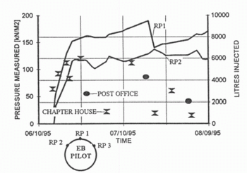
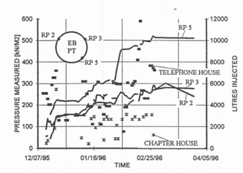
Figure 5. Detail Earth Pressure vs Time.
4.2 Observations
The reading results from both the earth pressure measuring devices and the shotcrete stress measurements indicate transient increases of loads being shed onto the tunnel due to Compensation Grouting.
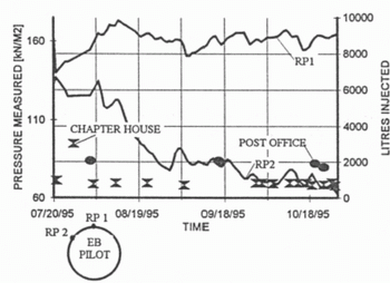
Figure 6. Details Earth Pressure vs Time.
Figure 7. Schematic Section through the eastbound
Platform Tunnel at Station 1223.
The maximum increase in the earth pressure measured was approximately 100 to 150 kN/m2. The shotcrete lining stress increased as much as 1000 kN/m2. The graphs displayed below indicate a higher increase of total loads/stresses, but these include also the growing ground loads being taken by the tunnel support. The values measured appear to very consistent with those measured at the Pilot Tunnel taking the larger tunnel size and the reduced clearance between the grouted area and the tunnel into account.
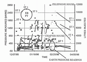
Figure 8. Pressure vs Time over five-months period.
Figure 9. Earth Pressure vs Time.
5 OBSERVATIONS AT 11.3 m TRIAL TUNNEL, Sta. 38
5.1 Situation
In the area of the 11.3 m Pilot Tunnel a series of trial Compensation Grouting passes were carried out. Frequent instrument readings were taken throughout these trials to collect detailed information on the influence of Compensation Grouting on the Trial Tunnel. Results from the trial ground treatment carried out in March 1995 were selected for this paper.
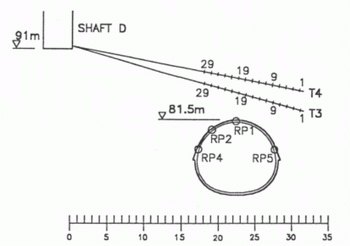
Figure 10. Sitatuion at the 11.3 m Trail Tunnel.
In total 5 sleeve pipes were installed above the Trial Tunnel roof to various depths. For this demonstration two pipes were selected that were located approximately 5 m (T 4) and 3 m (T 3) above the roof center line. Since the tube-a-manchette were inclined each individual sleeve was in a different distance to the tunnel and ground treatment extended beyond the tunnel width.The grouting was carried out in passes where every second sleeve was grouted. Accurate records of grout volume, grouting pressure and pressure measurement were taken throughout the trials as well some period after termination of the trials.
5.2 Observations
Similar to the previously discussed observations, the influence of the Compensation Grouting is of transient nature. It can be seen that increased loads/stresses dissipate after short periods. Consecutive grouting events lead to an accumulation of loads acting upon the tunnel that reached a certain maximum (approximately 50 kN/m2) but did not exceed these maxima. Effects measured at e.g. RP 4 may be interpreted as reaction to increasing lining loads being transferred into the ground. During grouting events the reading results also clearly indicate distinct pressure drops while other reading devices measured increases at the same time. This phenomenon may be explained by differential movement of ground elements which may have lead to pressure relieve in certain regions while others were loaded. Further investigation will be required to finally explain this occurrence.
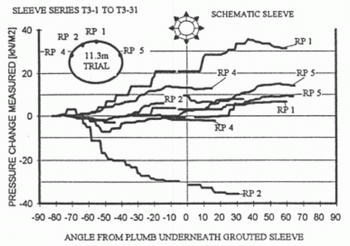
Figure 11. Relation between grouting location and monitoring device (Sleeve Pipe T 3).
Detailed time/load graphs indicate a dependancy of ground loads measured to the actual grouted sleeve location. Not only the distance between the grouted `spot' and the monitoring device but also the angle between grouted sleeve and the monitoring device appears to play a role. The grouting was carried out in passes that were progressing wave-like across the tunnel starting at the furthest end of the sleeve pipes. While a distinct change of earth pressure at effective angles (between plumb underneath the grouted sleeve and the measuring device) between approximately 60 and 30/20 degrees can be detected the zone directly beneath the grouted sleeve appears to be less effected. Most of the curves are ascending initially and show a drop of pressure or a stagnation when the grouted zone approaches the area directly above the measurement device. Only two curves indicates an increase of pressure between 10 and 0 degrees.
It appears that the closer to the monitoring device grouting is carried out, the less clear this trend is developed, but still stagnation prevails around 0 degrees. The graphs related to the grouting passes along sleeve pipe T 3 indicate a further build-up of earth pressure following the stagnation around 0 degrees whereas the most graphs related to T 4 show a clear decrease in pressure around 0 degrees and restart of pressure growth after that. These initial reviews of the data may lead to the interpretation that, under the given conditions, the maximum influence was not directly below the grouted spot but between 50 and 30 degrees from that. This may be related to a specific stress re-distribution behavior of this ground. However, more data will have to be processed and models to be developed to find a clear explanation of this phenomenon.
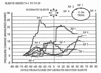
Figure 12. Relation between grouting location and monitoring device (Sleeve Pipe T 4).
6 POREWATER PRESSURE OBSERVATIONS
Compensation Grouting trials carried out to measure the porewater pressure changes during grouting passes were carried out. Generally, the reading results display pictures very similar to those described above. Transient pressure increases of up to 60 kN/m2 were measured. The readings indicate discrete increases and decreases of pressure during grouting events. Investigations as to the existence of zones being distinctively more influenced by Compensation Grouting than others will be carried out.
7 COMPENSATION GROUTING EXCLUSION ZONE
For the tunnel construction works at the station tunnels (Platform and Concourse Tunnels) an exclusion zone was developed, within no compensation grouting was allowed. This exclusion zone included the area above any unsupported tunnel section (freshly excavated round), the tunnel area where the shotcrete invert support was not completed and some distance ahead of the progressing tunnel excavation face. A rigorous procedure was introduced where during any grouting activity above the fully supported tunnel continuous visual and instrumented inspection of the lining behavior was carried out. The tunnel engineer in charge with these inspections was in contact via radio with the grouting operator and was empowered to immediately stop any grouting above the tunnel if any undue occurrence was detected. Threshold values assisted in the continuous assessment of the tunnel support conditions. As can be seen from the monitoring results no additional ground loads were transferred onto the tunnel which exceeded the design loads. Likewise, lining deformations measured did not indicate any 'weak-point' in the shotcrete lining that gave rise to concern.
8 CONCLUSIONS
The monitoring readings revealed basically three main aspects:
Firstly the tunnel lining was not over-stressed by the additional ground loads caused by the Compensation Grouting.
Secondly, the ground displays inhomogeneous response to the grout injection. Also differential movements of larger ground elements may have occurred that lead to localized load increase and relief.
Thirdly, the employment of Compensation Grouting in the vicinity of tunnels must be thoroughly assessed and potential ground load increases taken into account during the tunnel support design. Compensation grouting exclusion zones should be introduced depending on the project specific conditions.
REFERENCES
Anderson, M. 1995. Contract 104 Jubilee Line Extension Project - Additional Compensation Grouting Trial Pore - Water Pressure (unpublished report)
Kimmance, J. 1995. Contract 104 - London Bridge Station - Compensation Grouting Pore Pressure Study New City Court (unpublished report)
Kimmance, J. 1995. Jubilee Line Extension Project Contract 104 London Bridge Station - NATM Trial Additional Compensation Grouting Study (unpublished report)
Zeidler, K., et al, 1997. Surface Settlement Due to the Construction of the London Bridge Station Tunnels by NATM, World Tunnel Congress Vienna 1997, in: Golser, J., Hinkel, W., Schubert, W. (Editors), Tunnels for People, Vol. 1, pp.429-434.
