You are here
Design Concept for large Underground Openings in Soft Ground using NATM
June 12, 1990
Herndon, VA, USA
Design Concept for large Underground Openings in Soft Ground using NATM
International Symposium on Unique Underground Structures, Denver, Colorado, June 12-15, 1990
ABSTRACT
Since its introduction, the NATM has been adapted, modified and expanded. Today it is being used in ever softer ground and for a more diverse range of underground structures. Despite failures and setbacks, the evolutionary process of the NATM is far from over. As society begins to demand greater and more efficient use of underground space, skillful application of the NATM could well provide the necessary flexibility to realize cost effective excavation of future structures.
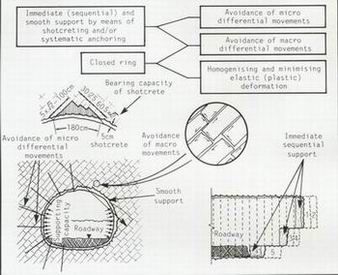
Creating an underground space by using all available means to develop the maximum self-supporting capacity of the rock or soil to provide the stability of the opening is accepted of by most civil engineers familiar with the concept, as the definition of the New Austrian Tunnelling Method (NATM). Rockbolts, lattice girders, wire mesh and shotcrete, instead of heavy timbers and steel arches, are used in various combinations to provide an elasticity in the initial support. This allows the stresses within the rock to relax and establish a revised equilibrium around the man made opening (MÜŒLER, FECKER, 1978). Once this self-supporting equilibrium is re-established, the ground will host the opening and maintain its integrity with the minimum of extra support. The ability to monitor the stress changes within the ground during excavation and understand how these recorded changes will effect the integrity of the opening is perhaps the greatest contribution by the Austrians in developing the concept, the principals of which, after all, are not new.
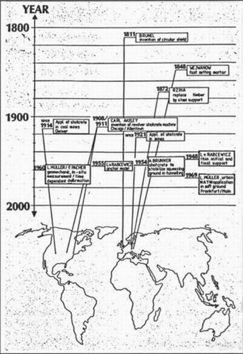
It was the mines head office of Pribram in Czechoslovakia in 1848 (Fig. 2) which first attempted the use of fast-setting mortar to avoid heavy timber support in a coal mine at Wejwanow (GRIMM, 1857). At the same time, Karl Ritter, a Swiss engineer, proposed a curved tunnel section with immediate closure of the invert to provide a closed ring in any squeezing ground, probably as a result of the 1818 patent of Brunel's circular soft ground tunnelling shield used under the River Thames in London.
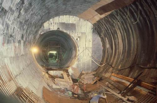
Figure 1: NATM applied on a step plate junction at the subway system in Frankfurt-Clay in 1968.
|
Rziha, the renowned nineteenth century German tunnelling engineer, professed that it is more skilful to prevent rock load than to handle it and that the difficulties of trying to handle heavy rock pressure are often related to the source of the pressure itself (RZIHA, 1872). Reducing loads by allowing the rock to deform before the final lining is applied is the principal behind the dual-lining support system introduced by Professor Ladislaus von Rabcewicz in 1948 (RABCEWICZ, 1948). The idea is based on theoretical investigations by Engesser in 1881 and was first applied by Schmid in 1926. In the meantime, shotcrete was invented by the taxidermist Carl E. Akeley in 1907 in Chicago as a method of protecting the skeletons of dinosaurs by spraying them with mortar. The original advocate of using shotcrete instead of heavy timber or steel arches as immediate support in squeezing ground was Anion Brunner, a little known mining engineer from Salzburg, Austria who, in 1954, had to assume full responsibility in order to use shotcrete to stabilize squeezing ground in a diversion tunnel for the Runserau power plant in Austria. One of the first publications (SATTLER, 1915) on design methods for the shotcrete shell was that by Professor K. Sattler which was based on research that subsequently appeared in a thesis (GOBIET, 1970) on the "shear failure" theory of shotcrete by Dr. W. Gobiet (Fig. 3). |
|
|
Application of the NATM on subsequent projects, particularly in urban areas, raised various different design considerations which could affect the success of using the method. For example, which of two metro tubes, one above the other, should be excavated first? Should the pillar of ground between two closely parallel tubes be replaced with a column of concrete (Fig. 5)? Under what circumstances and how quickly should the invert of a tunnel be undermined and closed forming a ring of immediate support rather than leaving the flat, unsupported floor of a more familiar NATM arched excavation? When should the planned immediate support regime be changed to suit either more difficult or much improved ground conditions?
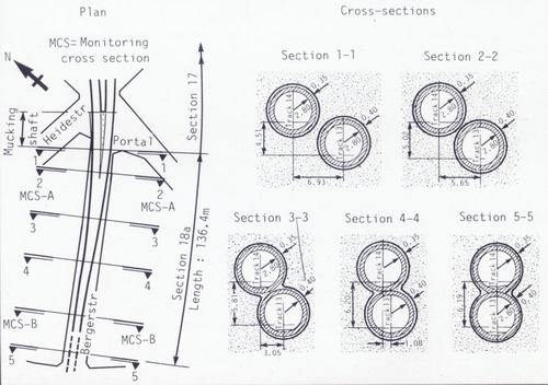
Figure 5: First NATM twin-tunnel bore in urban areas: subway, Frankfurt/Main 1971.
New ideas about solving these types of problems lay in the vast wealth of data obtained by previous scientific research into the field of soil and rock mechanics but it was the introduction of computers and computer analysis of sophisticated model tests that unlocked the secrets. This ability had hitherto been unavailable.
Delving into the theory of the method in this way meant not only that the concept would gain wide recognition and understanding but also that designers of NATM tunnels were ready to become more bold in their approach. Careful monitoring of changes in the behaviour of the ground during excavation should give the designer all the information he requires to specify the correct amount of support required by the prevailing ground.
Correct interpretation of the recorded measurements should provide a clear indication of what excavation sequence to adopt and what type and concentration of immediate support is required in the prevailing ground. For example, stress concentrations will lead to periodic contractions and deformation of bolt plates or cracks in the shotcrete shell if the support system is inadequate. Further investigations prove that ground bearing capacity can be sustained by avoiding convergence movements. Bringing the feet of the side walls in to within the distance between the spring line diameter will help avoid convergence but the ultimate is to undermine the invert and close the ring of immediate support as soon as possible if excessive convergence is measured.
Extensive modelling on stress concentration during tunnel excavation concludes that in unstable rock, the ring must be adequately supported within a distance equal to 1.5 times the tunnel's diameter from the face (SAUER, 1976) (Fig. 6). In ground of poor cohesion, the material inside the three-dimensional stress field at the face has to be supported. This can be achieved either by extending the support ahead of the face by forepoling with rebar, grouted crown bars or metal plates, or by leaving a wedge of unexcavated earth to prop the face, or in extreme cases, both.
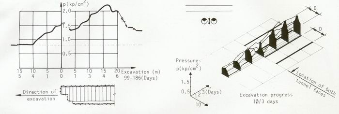
Figure 6: (left) Vertikal stress evaluation in centre of middle wall between two subway tunnels during
simultaneous and parallel excavation of tunnels.
Figure 6: (right) Vertical stress redistribution in whole pillar area.
In squeezing ground, the rate of excavation has to be adjusted to the setting rate of the shotcrete. The invert shotcrete, the final phase of closing the ring, must have the minimum strength to sustain the peak stress which occurs at a distance equal to 1.5 times the tunnel diameter back from the face.
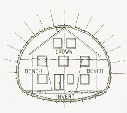
Depending on the ground site investigation studies, immediate support can range from as little as spot bolting where and when required in competent massive rock, to a systematic regime of bolts, lattice girders, mesh and shotcrete in less stable ground (Fig. 7). In extreme cases, the invert must be undermined and the ring of immediate support closed with wire mesh and shotcrete.
|
|
Unfortunately, as all tunnelling engineers will admit, ground conditions can never be guaranteed to remain as predicted by site investigation records. Even if the majority of the core samples predict good quality rock, the chances of there being zones of weaker if not totally noncohesive soil during the drive is quite high. At least, the contractor must be prepared for such an eventuality.
When using the NATM, such changes in ground conditions are covered by a series of different immediate support specifications (Fig. 8). With this flexibility, the most appropriate system can be engaged and the change effected in the most immediate time frame. Obviously, the greater the support necessary the more costly the tunnelmetre but equally applying the minimum amount of support necessary in either good or bad rock, keeps the cost per linear metre of tunnel also at a minimum.
|
 |
As could be expected, many early NATM projects where carried out in relatively stable ground and rock with a high self-supporting capacity such as sandstone, chalk, limestone etc. In such ground the concept proved highly successful and cost effective. Through the last decade, the record of successful NATM excavations for whatever purpose proves that the concept provides a highly cost effective tunnel in poor ground conditions also one which is neither over designed, thus wasting money on unnecessarily heavy or extra support, nor under designed to the point of jeopardizing the safety of the miners or risking failure or collapse either during excavation or after.
Unfortunately, the dividing line between the two objectives is very narrow and in the wrong hands, the concept can be easily abused. Success of the concept is based on appropriate contracting and relies heavily on the co-operation, mutual understanding and respect of all parties involved, more so than for any other tunnelling method. The owner, the designer, the contractor and his tunnelling crew all play a vital role in the day to day management and application of the method. Any breakdown in the relationship between the parties will lead to trouble and while there have been some outstanding successes using the NATM, there have also, for many different reasons, been some significant failures (WALLIS, Tunnels & Tunnelling, 1987).
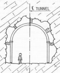
There are two principal causes for a failure or collapse. One is design error and the other is the human factor. The behaviour of the structure, like all underground excavation, is influenced by unpredictabel water conditions, unforeseen geological, geotechnical and tectonic anomalies. The accuracy of instrument measurements and the skill of the designer and the competance of the miners should be able to cope with most of such anomalies. However, if the measuring stations are in the wrong places along the tunnel, or the initial support measures are inadequate or modified too late, or if warning signs have been ignored in efforts to increase excavation rate and/or to minimize support costs, failure is almost inevitable (Fig. 9).
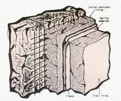
While the results and interpretation of measurement readings are important, their value is heavily influenced by what instruments are employed (Fig. 10), how frequently they are read and where they are stationed. Convergence, roof settlement and other deformation measurements are common practice and valuable, but they give little indication of the actual stress in the shotcrete shell which is more important to the assessment of the failure potential (PACHER, SAUER 1980). Flat hydraulic pressure cells, first introduced in 1958, are still the only available instruments for measuring such stress.
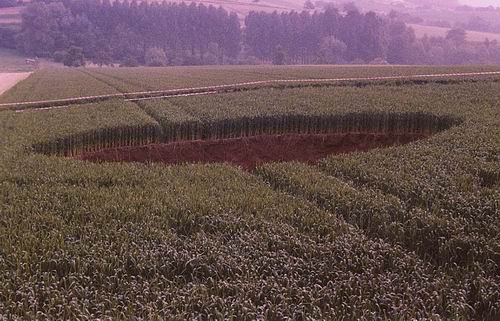
Figure 9: Downfall on a railway tunnel in West Germany 1984.
With so many variables influencing the excavation of underground space, the need for a flexible design concept should be obvious. A too rigid determination of initial support adopted as a result of calculations, excavation design or construction plans, will restrict the flexibility that is essential from all parties. Furthermore, it will reduce the natural feeling of responsibility of the miners at the face and allow scope for failure due to what is known as the human factor.
Once the designers, armed with information about the ground behaviour, have specified a plan of action, it is up to the tunnelling crews and their supervisors to carry this out. The need to employ skilled miners as well as experienced supervisors in the execution of excavation according to the NATM principals cannot be understated. The direct reaction of the miners and their supervisors to the given rock conditions, which includes their interest in their own safety, is an essential component and as important for the NATM as for any other free-face mining method. Planners, consultants and construction supervisors should always be aware of this and try to take advantage of the skill of an experienced tunnelling crew. Inexperience in the crew will lead to unnecessary risk-taking in the interests of speed or high production rates, particularly during the third or night shift when higher authority is absent and any stop could mean loss of the entire shift's production.
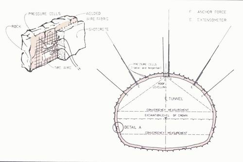
Figure 10: Typical Monitoring Cross Section and Pressure cells applied in shotcrete.
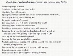
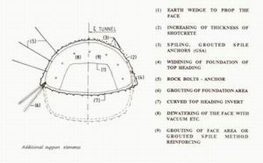
But it is from failure or dealing with potential collapse situations that perhaps most has been learned for the development of the concept. The excavation sequence of an NATM project now includes a much greater number and combination of excavation sequences than it did in the past and the available means of developing the maximum self-supporting capacity of the rock or soil have grown substantially as new products and materials have been introduced to the market.
The importance of closing the ring of immediate support is now well chronicaled and accepted by skilled users of the method. The appropriate distances between a top heading and bench excavation can now be calculated with greater accuracy. When and if the invert needs to be undermined and closed to ensure the integrity and stability of the opening while still maintaining the flexibility in the immediate support to allow the rock stresses to relax and reestablish the self-supporting equilibrium can also he predicted with confidence.
There should no longer be any hesitation about taking the appropriate course of action when ground conditions deteriorate. There may be several possible alternatives but only by keeping in mind the objectives of the concept will the most appropriate be selected.
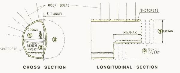
Figure 11: Excavation sequences on a halfed cross section.
The excavation area may need to be reduced to several smaller headings such as side wall drifts (Fig. 11 & 12). It may require halving the advance per round from, for example, 3m to 1.5m. It could mean increasing the reinforcement of the shotcrete by extra lattice girders, more wire mesh or by adding steel fibre to the mix as well as increasing its thickness. It may even require a decision to open up the bench and gain access to the invert in order to close the immediate support ring of the full cross section earlier than programmed.
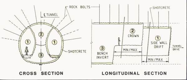
Figure 12: Sidewall drift method for wide excavations.
In making decisions about any of the above, the client, consultant, contractor and construction supervisor all have a vital role to fulfil and only by mutual agreement will safe progress continue. Clients, in a less traditional role, become more closely involved in such decisions since they are paying for the structure and an increase in immediate support, or a change to the excavation sequence in order to cope with poorer ground will result in a higher cost per tunnel metre. But refusal to pay the extra cost when required, could well result in much higher cost in the long run if there is a delay in the change of strategy, or if only half of what is recommended is granted.
Unfortunately, embracing the responsibility of an NATM option is not always easy and even if the NATM has been adopted by all in the beginning, confidence and courage fails all when poorer ground conditions are encountered. There are unfortunately several examples throughout the world where the NATM has been adopted in great confidence at the outset of a new project, again for its economic and application advantages, and all goes well until the ground begins to deteriorate unexpectedly.
Under such circumstances, inexperienced NATM practitioners, due to fear, tend to fall back on old, long established, conventional design parameters. Instead of staying true to the principals of the NATM concept, they will often stop the works and revert to the installation of heavy steel, both of which often cause rather than prevent an ensuing collapse.
Halting progress can be as damaging as too much haste in causing a collapse or fall. The time of inactivily will allow the relaxation and concentration of excessive stress under which no amount of propping or support will hold back. Installing heavy steel arches (Fig. 13) will not prove effective in the long run either. Arches, no matter how heavy nor how closely installed, do not increase the strength of the surrounding material. They support only locally and because they cannot provide smooth and uniform contact with the ground along their full length, they allow too much ground movement to ensure stability. Instead, ground movement should be controlled by increasing the number and length of rock bolts as well as increasing the thickness of the shotcrete and its reinforcement with extra lattice girders, wire mesh or steel fibres.
|
In addition the excavation should be modified to keep the excavation section as rounded and as close as possible to a circular section. This can be done immediately by moving the feet of the side walls closer together to at least within the diameter of the tunnel at spring line. It is most effectively achieved by undermining the invert and closing the invert with wire mesh and shotcrete. Indeed there are now several different methods of dealing with bad ground while remaining true to the principals of the NATM which is to use every available means of developing the self-supporting capacity of the soil or rock which will allow the necessary deformation while preventing the development of rock load. However, despite the complexities of the concept, the extra responsibility and involvement required by the client, as well as the recorded failures, the NATM is still a highly respected tunnelling method which is finding wide recognition and application throughout the world both for its economic and application advantages. |
|
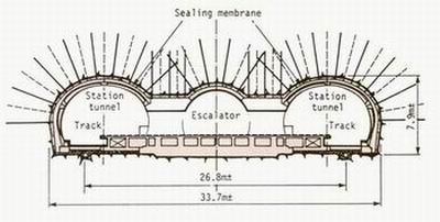
The next significant break through for the concept was its introduction to the United States and its application in 1983 on the B10 section of the Washington D.C. Metro for the Washington Metropolitan Area Transit Authority (WMATA), the client. Submitted as a value engineering cost proposal, the NATM cost estimate was $-US 48 million as opposed to the owner's estimate of $-US 80 million for conventional methods. In addition, a full pvc waterproofing system was installed between the initial shotcrete lining and the final in-situ concrete lining. The contract, which includes a 13m high x 18m wide (164m2) double crossover and the 8.7m high x 11m wide station tunnels (Fig. 7a), was successfully completed between 1983 and 1987. Today, it provides a clean dry structure which was recognized in 1986 with an award from the Society of Civil Engineers in Washington D.C.
|
|
The concept has also been recognized by the British construction industry following its application for the construction of a diversion shaft on a water supply project in Birmingham in 1988. A connection had to be made between an old water tunnel and its new adjacent replacement. The shaft sunk to execute the junction had to be sure not to exert damaging load on the old tunnel which had to remain in service (luring excavation (Fig. 15). Using the NATM lead to a safe and economic solution for this tricky structure and won the 1989 awards of the British Construction Industry.
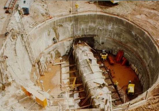
Figure 15: NATM shaft design for a diversion of the water main Birmingham, U.K 1989.
The method has also been submitted as a design alternative for some spectacular underground structures but which, for various reasons, not least of which is unfamiliarity with method, was not adopted.
One such project was the 406m-long Mount Baker Ridge highway tunnel in Seattle, Washington State in the United States in 1982. Instead of the 24 concrete-filled drifts from within which the single bore tunnel was excavated, the NATM alternative, based on a finite element calculation, proposed a molti-phased excavation sequence to provide the necessary 250m2 cross section into which six traffic lanes would have been fitted (Fig. 16).
Another soft-ground NATM alternative was prepared for a section of the Boston Central Artery project to place the existing elevated highway underground. Much of the work is designed as cut-and-cover tunnelling but at one point the alignment passes under an existing metro station where a mined operation is required. A multi-phased soft-ground NATM design was proposed instead of the chosen pipe jacking forepoling option (Fig. 17).
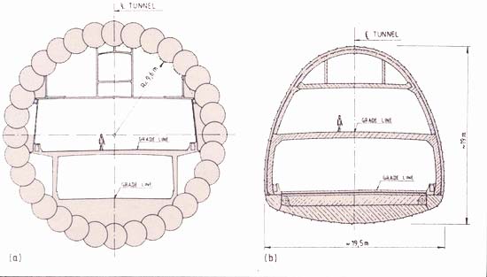
Figure 16a: Original design.
Figure 16b: NATM alternate of the Baker Ridge Tunnel, Seattle 1982.
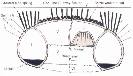
Figure 17: Central Artery, Boston: A multi-phased NATM alternative for the metro station underpass.
But such large structures are being built using the NATM in soft ground in other countries. For example, the hugh car park cavern at Landsberg, with a size similar to the Mount Baker Ridge tunnel, is currently being excavated in soft ground just northwest of Munich in
West Germany (DRESSLER, 1990). A paper concerning this interesting and remarkable project is being presented during this conference (Unique Underground Structures Denver - June 1990) by Dr. Dressler. Although based on the NATM, an alternative excavation sequence was also prepared for this project to help cope with the soft ground conditions encountered at this site (Fig. 18).
The alternative is for a pretzel type excavation sequence with an advancing crown drift to explore the geology and secure the roof in the first phase. An earth wedge propping the face provides access to the crown heading while the side walls of the entire cross section rest on curved shotcrete hooks (pretzel-footing) to allow smooth stress redistribution around the opening. The invert is constructed in a later step in slices by using in-situ concrete.
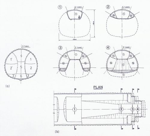
Figure 18: Landsberg Cavern near Munich, West Germany
a) Sidewall drift designed by the client.
b) Alternative Excavation proposal.
On the Channel Tunnel fixed railway link between Britain and France, the NATM is being used to excavate the first of two large double-track crossover chambers under the sea. Excavation of the 163m-long x 21.3m-wide x 15.4m-high cavern is being excavated using the side wall drift sequence under a cover of only 36m between it and the 31m depth of the sea above (Fig. 19a) started in September 1989. The usually central service tunnel is 40m to the north of, and 9m deeper than the alignment of the running tunnels which come together for the crossover (Fig. 19b).
Excavation of a similar undersea crossover chamber from the French coast will start later this year (1990).
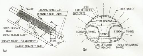
Figure 19a: Access to the Channel Tunnel crossover from service tunnel.
Figure 19b: The construction stages of the UK crossover cavern.
These are just a few examples of the increasing number of underground structures including underground power house caverns, defence installations, sewer treatment plants and oil storage caverns which have, and are being, successfully constructed using the principals of the NATM.
And the NATM is still in its relative infancy. With advances in the Field of soil and rock mechanics aided by further sophistication of ground instrumentation and developments in the equipment and materials used to carry out an NATM excavation, the economic and application advantages already achievable can be successfully applied to more varied types of unique underground space structures and in more complex ground conditions. The flexibility afforded by an NATM operation, not only in its construction sequence but also in the writing of the contract documents, a project's budget and its construction schedule is more easily controlled, greatly increasing the probability that the project will he completed on time and within budget.
REFERENCES
Dressler, "Construction of a Shallow Underground Parking Station", International Symposium on Unique Underground Structures, Denver, Colorado, (June 12-15, 1990).
H. Edeling and W. Schulz, "Die Neue Österreichische Tunnelbauweise im Frankfurter U-Bahnbau", Bauingenieur, 47 (Oct. 1972), 351-62.
W. Gobiet, "Beitrag zur Berechnung von Tunnelauskleidungen", Dissertation, Technische Universitit Graz (1970).
J. Grimm, "Ober die bei dem Aerarial-Steinkohlenwerk zu Wejwanow versuchsweise vorgenommene Instandhaltung der Grubenstrecken mittels Kalkmörtelbewurf', Bern- und Huttenm. Jahrbuch, Leoben Pribram (1857), 7, 157-62.
H. Krimmer and G. Sauer, "Die Neue Österreichische Tunnelbauweise im U-Bahnbau: Rück und Ausblick", Felsbau. 3, no. 3 (1985), 129-35.
L. Müller and E. Fecker, "Grundgedanken und Grundsätze der Neuen Österreichischen Tunnelbauweise".
Grundlagen und Anwendung der Felsmechanik: Felsmechanik Colloquium,
Karlsruhe, 1978, Clausthal: Trans Tech. Publications (1978), 247-62.
F. Pacher and G. Sauer, "Gedanken zur Auslegung von Tunnelausschreibungen und zum Stand der messtechnischen Bauwerksüberwachung", Rock Mechanics Supplement, 10, (1980), 197-205.
L. von Rabcewicz, "Verfahren zum Ausbau von unterirdischen Hohlräumen, insbesondere von Tunneln", Austrian Patent 165 573 (1948).
F. Rzhia, "Lehrbuch der gesamten Tunnelbaukunst", Band II, Berlin (1872).
K Sattler, "Österreichische Tunnelbauweise - Statische Wirkungsweise und Bemessung", Bauingenieur, 40, no. 8 (1965), 297-301.
G. Sauer, "Spannungsumlagerung und Oberflächensenkung beim Vortrieb von Tunneln mit geringer Uberdeckung unter besonderer Beriicksichtigung der Mittelwandbelastung beim synchronen und asynchronen Doppelröhrenvortrieb", Dissertation, Institut Mr Bodenmechanik und Felsmechanik, Universität Fridericiana, Karlsruhe, no. 67 (1976).
J. Spang and K. Zimmermann, "Der Neubau des Schwaikheimer Tunnels", Strassen- und Tiefbau (1967), 404-11.
S. Wallis, "Counting the cost of NATM downfalls", Tunnels & Tunnelling, 19, no. 10 (Oct. 1987), 16-20.
Click here to see the full document (application/pdf, 2582 KB).