You are here
Achieving a dry tunnel
Achieving a dry tunnel
RETC 1987
Rapid Excavation and Tunneling Conference, June 14-17, 1987
ABSTRACT
Generations of tunneling engineers had to fight not only against bursting rock and squeezing ground but also against the destroying power of water. Intrusion of groundwater into the tunnel opening affects the stability of the tunnel support system, reduces the safety of the traffic inside the tunnel, induces corrosion of installed equipment, and provides for creeping currents at electric facilities.
INTRODUCTION
Aware of these problems, engineers of the Washington Metropolitan Area Transit Authority and their consultants opened the way for a new approach in sealing a tunnel. It was made possible by accepting a new method of tunnel construction scarcely applied in the U.S. before. This new technique, the New Austrian Tunneling Method (NATM), provided the basis for the successful installation of a PVC-membrane between two separated shells of tunnel lining, and the carefully directed drainage of groundwater. Beside of the economic benefits already attained by applying the NATM for tunnel construction, the Authority now saves millions of dollars otherwise necessary to maintain the tunnel during its lifetime (Garrett, 1986; Setzer, 1986).
But there is a large number of leaking tunnels built according to conventional methods, some of them facing severe problems jeopardizing the safe utilization of these structures. Recently developed methods indicate that even those tunnels can be rehabilitated without extensive costs by draining and sealing them afterwards. A road tunnel in the Austrian Alps provides the scene for a major attempt to convert one of those leaking tunnels into a dry structure.
LEAKING TUNNELS
Expectedly, tunneling activities spread rapidly all over the world during the last few years. Increasing industrialization boosted the demand for supply lines such as potable water tunnels, sewer tunnels, or pressure tunnels for distribution of electric power. The evergrowing needs for transportation led to the improvement of existing highways and freeways, and to the development of new high-speed railway tracks to connect larger cities, both calling for the employment of underground structures to allow for smooth routing and environmental conservation. In many larger cities the need arose for the development of an effective rapid-mass-transport-system, which almost inevitably includes a far reaching underground traffic network.
The rising demand for tunnel construction consequently led to the development of safer, faster, and more economic tunneling methods than those applied ever before. But still, a tunnel is considered as something that leaks (figure 1). Fracture zones in high overburden rock characteristically discharge fissure or crack water into the tunnel opening, soils containing sands and gravel detrimentally lead surface and groundwater through the tunnel lining into the cavity.
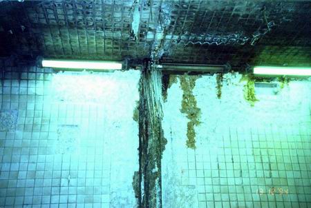
Figure 1: Leaking Highway Tunnel.
Conventional methods to obstruct water intrusion, consisting basically in grouting the tunnel lining and the surrounding ground, failed mostly because of the impossibility to seal off every small fissure in and around the tunnel support system. Likewise, placing of reinforced concrete lining to reduce cracking usually prove insufficient, as does the use of tiles or synthetic coatings applied on the inside face of the tunnel lining (Joye, 1986). In contrast, long-term behavior of both surrounding ground and support system adversely affects the sealing system and promotes an ever increasing infiltration of water during tunnel operation.
As a result, running water, calcification, and ice formation in traffic tunnels (figure 2) significantly increase the costs for tunnel maintenance necessary to assure the safety of passengers and personnel. But even more, the special condition of abundant humidity induces deterioration of concrete and corrosion of reinforcement, steel support, machinery and equipment. For that reason, especially when the tunnel is exposed to frost or stray current, the intrusion of groundwater is threatening the serviceability of many an underground structure. And there is no solution to the problem?

Figure 2: Ice formation at the Felbertauerntunnel in Austria NEW APROACH TUNNELING.
One of the new tunneling techniques developed during the phase of increasing demand for tunnels of all kind was the "New Austrian Tunneling Method", or NATM, called so because of the decisive participation of Austrian engineers on the development and improvement of the method. This new technique of tunnel construction comprises not only the use of special materials as shotcrete or rock bolts and the like, or a special way of excavation sequences and processing, but merely a completely different philosophy compared to conventional techniques. According to this new philosophy , the following principles have to be observed (Mueller/Fecker, 1978):
-
The tunnel support system is to be conceived as a compound structure consisting of rock or soil formations surrounding the cavity, and of the various means of support such as anchors, shotcrete lining, steel ribs etc.
-
Damage causing loosening of the original rock structure or soil formation has to be avoided to maintain strength and stability of the tunnel support system; contrarily, deformation of the initial lining cannot be avoided and is necessary to activate the load carrying capacity of the overall ringlike support system.
- The tunnel structure acts as a tube in a four-dimensional way, being time the most important parameter; accordingly, the initial lining must be installed at the appropriate time, and the completion of the invert arch must be considered as a function of stress distribution, soil characteristics, and excavation advance rate.
- The immediate and smooth contact of the initial lining to the excavation surface is important, as is its ductilibility. A certain slenderness of the lining without unnecessary and wasted means of support has to be achieved; increasing the lining's stiffness cannot significantly affect ground movement, but will increase parasitic lining stresses resulting from imposed ground movement (Kuesel, 1986).
- The choice of the best cross section is important, while allowing for extensive adaptation to varying geomechanical conditions and operational needs;
- The parameters for design of lining and heading process are found and checked empirically, so that monitoring becomes a integral feature of this method. The inner or final lining must be designed so as to allow for long-term redistribution of rock or soil pressure considering the weakening or total failure of the initial lining.
- The driving method has to be adapted to the ground conditions encountered. The advance rate, depth of round, and the right choice of portioning the face into separate headings play an important part in achieving a safe, economic, and operationally feasible driving method.
Put all together, this new method brought not simply some modifications and improvements to already existing techniques, it rather revolutionized practice and theory of tunneling by providing a completely new geomechanical concept. First employed by A. Brunner within a fault zone in an Austrian diversion tunnel to avoid the heavy timber support which otherwise had to be applied to handle the squeezing rock conditions (Brunner, 1958) it turned out to be generally a very suitable and gentle method for soft-ground tunneling (Sauer/Lama, 1973; Krimmer/Sauer, 1983; Heflin/Irshad, 1987). But by the time, it displayed still another important merit.
THE WATERPROOFING SOLUTION
In 1948, L. v. Rabcevicz patented a tunnel lining consisting of two completely separated shells as a further development of the NATM (Rabcevicz, 1948), and several years later the idea of putting something in between to seal off groundwater led to the next step.
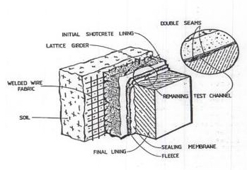
Figure 3: NATM and Sealing Membrane.
The shotcrete of the initial lining provided yet a relatively smooth surface to support any kind of sealing, and the concrete of the final lining would protect it from being damaged during tunnel operation (figure 3). However, the problem consisted in finding the right material to suit all of the many technical requirements that must be claimed of a permanent waterproofing system. To meet the actual standard of knowledge, these demands have to include at least the following items:
The waterproofing system must provide a continuous enclosure of the areas critical for intrusion of groundwater. It must be able to adapt to the discontinuities of the surface.
The imperviousness of the waterproofing system must remain permanently despite of rheological or structurally caused movements (long-term behavior of ground, temperature variation, vibration, or shrinking and creeping of concrete).
- The waterproofing system must be able to bridge small cracks in the construction surface. It must also be able to absorb discontinuous stress variations and, to a certain extend, in-plane forces without being damaged.
- The waterproofing system must be resistant to all types of aggressive water, nether from natural sources or leached from concrete, and resistant to biological attacks.
- The waterproofing system must be suitable for installation on damp and wet surfaces. It must be easy to handle and to install. Installation must be possible in large quantities with the help of reliable, mechanized methods.
- The used material must be self-extinguishing in case of fire. -
- It must be possible to check the waterproofing system for potential damage and to easily repair it before placing the final lining.
First investigations and attempts in that direction have been made in the early sixties in both Switzerland and Austria, basically consisting of applying asphalt membranes and, later on, sprayed insulations reinforced with glass-fibre and based on plastic or bitumen-latex. But as promising as these trials were, they never revealed full success.
Ten years later a new system was developed, combining a non-woven polypropylene geotextile and a high-polymer sealing material. The excellent results, obtained in the course of the construction of several important road tunnels crossing the Alps, consequently encouraged Austrian and Swiss engineers to apply this new waterproofing membrane to subway and railroad tunnels and even shafts (Meggl, 1980; Gerhard, 1983; Treichl, 1984). Soon afterwards, the method was adopted, together with the NATM, by most European countries, and its employment was initiated all over the world.
WASHINGTON'S SUBWAY TUNNELS
From 1966 to 1986, the Washington Metropolitan Area Transit Authority has been building 70 miles of a rapid rail transportation system planned to cover 103 miles when finished. This system serves the nation's capital, connecting it with the surrounding areas in the states of Maryland and Virginia. Included in the transit system are ten stations and about eleven route miles of twin subway tunnels excavated in bedrock (Garrett, 1985).
Prior to 1983, the favored method for constructing these subway tunnels was employing a boring machine because of the arrangement of construction contracts, and for other economic considerations. Where drill-and-blast methods had to be used, the excavations were initially supported by steel ribs and, when required, rock bolts and shotcreting. Final tunnel linings were constructed using reinforced cast-inplace concrete. In order to prevent intrusion of groundwater through the lining, the consolidated placement of concrete was supplemented by cement grouting. But despite of all efforts, the structures remained as they were ever since tunnels have been built: leaking (figure 4).
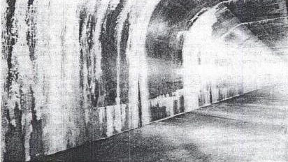
Figure 4: Leaking WMATA Tunnel.
In 1983, Section B-10a of the Glenmont Route was advertised. The works basically comprised the construction of 14,450 ft of singletrack tunnel with a cover of 120 to 200 ft. Included were also a 200 ft long chamber with a clear span of 50 ft and a rise of 35 ft to accommodate a track crossover, further the 600 ft long Stockholm type Wheaton Station, and a 250 ft long escalatorway, all to be constructed by means of subsurface excavation. Additionally, five ventilation and fan shafts had to be put down. Six contractors submitted bids, the lowest one being presented by ILBAU-America, a subsidiary of an Austrian construction firm. Initiated by the first author, the contractor submitted a change proposal immediately after award to accommodate the application of the New Austrian Tunneling Method for the Section B-10a (Egbert, 1984; Gay, 1986).
NATM IN THE UNITED STATES
After some of the NATM-specific features have already been included in the design of the Mt. Lebanon light rail tunnels in Pittsburgh, Pennsylvania, the Section B-10a was bound to be the first tunnel in the United States thoroughly redesigned according to all the principles of the new tunneling technique(Cavan/Rhodes/Mussger, 1985). Assisting the contractor in this design conversion were Dr. Gerhard Sauer and Geoconsult from Salzburg, Austria, coordinated in the USA by the firm of Law/Geoconsult of Atlanta (Martin, 1984; Wallis, 1985).
About ten different cross-sections of the original layout had to be redesigned. First of all, the existing tunnel shapes were modified to accomplish a ringlike supporting rock structure around the cavity. Then, the initial lining was designed as reinforced shotcrete, and the final lining of generally unreinforced cast-in-place concrete (Gnilsen, 1986) or, for larger openings, a second layer of reinforced shotcrete. Because of aesthetic reasons, a coffered pre-cast concrete liner was used as part of the final lining of the Wheaton Station (Heflin/LeFevre, 1985).
The B--10a tunnels and the lower parts of the shafts are situated in metamorphic rock (quartz-mica schists and quartz-diorite gneiss), which is weathered, jointed, and sheared in varying degrees. Since NATM calls for adapting the driving method and advance rate to the varying ground conditions and to use the initial support means as economically as possible, tunneling conditions were subdivided into three rock classifications in the new design, using shotcrete reinforced with welded wire fabrics rock bolts, and lattice girders as basic elements of the initial tunnel support (Heflin 1985; Irshad, 1986). Design computations were performed using a finite element method (FEM) analysis (Gnilsen, 1985).
In late 1983, while riding the subway to present the NATM concept to WMATA's Board of Engineering Consultants (BOEC), the first author of this article realized the amount of seepage coming into tunnels and some station areas of the existing system. Later at the presentation, he offered dry stations, shafts, and tunnels by proposing to include the recently developed waterproofing system into the design of Section
E-8 a .
FIRST DRY TUNNEL
According to the experiences gained with the new sealing method in Europe, the General Engineering Consultants supported the recommendation to include the PVC-membrane system into the design to an additional cost of about $250 per linear foot, equal to 2.5% of the total costs of tunnel construction. Considering the maintenance problems that WMATA has encountered resulting from leakage, the authority agreed to the suggestion and subsequently approved the waterproofing system as part of the VECP early 1984 (Garrett, 1986).
This waterproofing system was based on prevailing European concepts (figure 5). Accordingly, the shotcrete of the initial lining provided the basis for the installation of a sealing membrane comprising two layers of geosynthetics subsequently attached to the shotcrete shell.
The first layer, a needle-punched or bonded non-woven polypropylen geotextile, is used as a fleece backing, and fixed to the shotcrete by means of special PVC disks and fasteners. The fastening disk is designed to support the second layer, a geomembrane which will then be heat-welded onto it, but to fail in case of overstress during the casting of the final lining still before the plastic sheet gets damaged. Special attachments are used in combination with these fasteners in areas where reinforcement of the final lining has to be kept in place. Details of the two main elements of the waterproofing system can be described as follows:
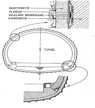
The fleece backing: it is assigned (1) to protect the subsequently installed geomembrane from sharp projections on the shotcrete surface when the casting of the inner lining forces it to back against the shotcrete, and (2) to promote drainage of the groundwater down to perforated drain pipes on both sides of the tunnel.
The permanent mechanical protection and drainage function of the geotextile layer is of decisive importance for the lasting effective ness of the total sealing system. Therefore, the following technical requirements have to be claimed:
- The protective non-woven geotextile must have a certain strength and extendibility to resist the stress and strain mainly caused by the attaching operation and the concrete pressure during casting of the final lining. The geotextile has further to cope with high tear stress when in contact with the partly sharp-edged surface of the shotcrete.
- The protective non-woven geotextile must have a certain water permeability within the plain to assure free drainage of seepage water to the drain pipes at the bottom.
- The geotextile has to be chemically resistant to all typos of groundwater. Especially calcium hydroxide and other aggressive components found in hydraulic binders must not harm the fleece.
The waterproofing membrane: installed next, it is (3) the actual sealing element of the system, assigned to keep off groundwater from the tunnel's interior, but also (4) a separating element to protect the concrete of the final lining from eventually being deteriorated by aggressive water seeping through the shotcrete lining, and further serves as (5) a gliding element which reduces the shrinkage cracking of the final lining, or contrarily allows to cast larger lining segments monolithically.
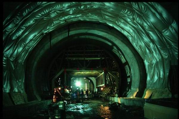
Figure 6: NATM Waterproofing System at WMATA's Section B-10a.
This geomembrane is made of a polymeric material and manufactured as impervious sheeting approximately four feet wide. In a first step, the sheeting is radially attached onto the initial lining by heat-welding it to the earlier installed PVC disks, which have been spaced with an interval of about 3 feet to each side. In a second step, the sheeting is made longitudinally continuous by double-welded seams. Portable equipment is employed to fuse, via a hot wedge, these seams between the geomembrane sheets. Finally, the seams are checked with compressed air for tightness, while the remaining area is visually inspected. Material injury caused by construction equipment or steel reinforcing will be detected due to a colored signal layer contained in the membrane, and can easily be repaired by applying a heat-welded patch to the tear. Beside of the quality control of the delivered material itself, this method has been proven adequate the assure a functioning sealing membrane.
Frequently, European tunnel specifications refer to the geomembrane as a "high-polymer" material, in order to distinguish it from polymerblended ones. For the Washington project actually plasticized polyvinyl chloride (PVC-soft) was used. In other cases, high density polyethylene (HDPE) or ethylene copolymer bitumen (ECB) have been used as well (Gnilsen/Rhodes, 1986).
The technical requirements for the geomembrane are not very different from those claimed from the geotextile, and consist basically in the following:
- The high-polymer geomembrane must have a certain tensile strength and ductilibility to allow for adaptation to the irregularities and roughness of the shotcrete lining. On the other hand, shotcrete recess must be restricted.
- The same tensile strength in both sheet and weld must be attained. Welding test specimen must be examined to secure this high level of quality.
- The geomembrane must also have sufficient tear resistance to endure- the concrete pressure during casting of the final lining, and enough thickness to withstand the assumed hydrostatic pressure.
- As with the fleece backing, the high-polymer geomembrane must lastingly defy biological and chemical deterioration, and especially resist the aggressive chemicals set free by the cement of the final lining's concrete.
- To avoid hazards to the safety of the tunnel crew, all geosynthetics used in the tunnel must also be highly fire resistant, defined by its self-extinguishing capability. On the other hand, these geosynthetics must not loose their technical characteristics when exposed to cold temperatures.
To ultimately define the characteristics required for both geotextile and geomembrane, German DIN codes served as a basis for the specifications incorporated into WMATA's contract documents for Section B-10a, transformed to ASTM standards to conform with American practice.
Beside of the design work concerning the actual sealing system, the problem of calcification within the drainage system had to be resolved. Field observations and laboratory tests led to the conclusion that precipitation of solids in the groundwater results from both evaporation and chemical reaction of components in free air with materials dissolved in the water. Consequently, a continuously flowing drainage system was developed that limited exposure of groundwater to free air (Leonard, 1986).
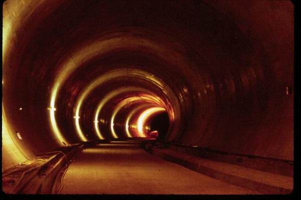
Figure 7: WMATA's NATM Section b-10a.
After an extensive review conducted by WMATA and its General Engineering Consultant, the Value Engineering design using the New Austrian Tunneling Method finally achieved approval. While construction works were in progress, a view at the shotcrete of the initial lining provided strong evidence of groundwater intrusion at almost every location of the tunnel, emphasizing the need for an effective and reliable waterproofing system. An inspection of the as-built underground structures of WMATA's Section B-10a now easily reveals that the efforts of redesigning the tunnels were crowned with complete success, converting these structures into what they are said to be: the first real dry tunnels in the USA.
REHABILITATION OF EXISTING TUNNELS
Once enjoying the merits of dry tunnels built according to the method described above, the question arises: could materials and methods similar to those be applied to sealing off existing tunnels built according to conventional techniques as well? The answer is "yes," as the example of the Austrian Felbertauern Tunnel reveals.
Crossing the Austrian Alps at a height of about 5,000 ft above sea level, the Felbertauern Road connects the southern part of Germany with the industrial area of northern Italy. The most important structure along the course of the generously routed freeway is a 17,500 ft long two-lane tunnel, situated in sound metamorphic rock interrupted by some fault zones. It was built in 1966 to 1968 with conventional drill and blast methods, using mainly rockbolts and only occasionally steel sets and shotcrete as means of the initial tunnel support. Cast-in-place concrete with a thickness of about 16 to 20 inches was used as tunnel lining.
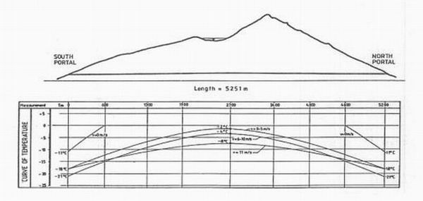
Figure 8: Felbertauern Tunnel Temperature Curve.
Due to the fault zones, major groundwater inflow occurred at three sections along the alignment of the tunnel, and at the portal areas. Attempts to control the flow of groundwater and to keep the tunnels interior dry consisted basically in collecting all seeping groundwater into flexible drain pipes attached to the rock surface (Oberhasli Method) and drawing it into the main tunnel drain.
But soon after completion of construction works, groundwater intrusion through the tunnel lining was obvious, affecting about 45% of the total length of the tunnel. All of the well known dilemma now clearly appeared: wet road surface, calcification, formation of ice and deterioration of the tunnel lining, as well as the psychological effect on the motorists (figure 1 and 2). Several approaches in subsequently sealing off the tunnel and permanently curing the concrete by means of grouting, later by inserting additional drains into the tunnel lining failed. Eventually in 1985, a contract was given to the first author to develop a reliable system to allow for a complete rehabilitation of the tunnel.
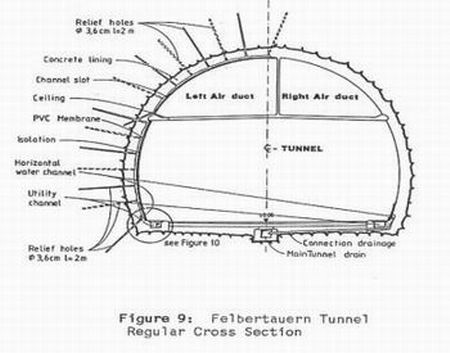
Investigations started with an analysis of the temperature curve developing along the tunnel's alignment in correlation to different wind speeds within the tunnel (Figure 8). As temperatures fall to about -20?C and stay below the freezing point for many month of the year, the insolation of wet tunnel lining and drains became very important. Then, the appropriate means of collecting the water had to be found. Conditions can basically be divided into two categories: single groundwater intrusions, and merely large seeping areas. Where local and concentrated inflow of groundwater can be recognized -- most likely leaking through shrinking cracks in the concrete lining -- a vertical slot or channel will be cut with a stone saw, about 3x3 in. wide.
From here, a row of relief holes will be drilled 7 ft deep and in divergent directions to draw the water into the channel. Near the bottom of the side walls, another horizontal or rather slightly inclined channel is cut to collect all water coming from an area of about 100 to 200 ft of tunnel length. These channels final 1 y 1 ead to manholes connected with the main tunnel drain, which is situated at frostfree depth beneath grade at the tunnel s centerline. (Figures 9 and 10).

The heart of the sealing system, however, is still the PVC-waterproofing membrane as described in the previous chapters. Specifications for this geomembrane are generally the same as for those employed at tunnels designed according to NATM principles, and so are the requirements for the entire system. The difference lies primarily in the fact that no second concrete lining is available to protect the membrane against physical damage. As a substitute, some other resistent material has to take its place. In the case of the Felbertauern Tunnel, corrugated aluminum sheets will be used. These sheets will also carry and protect the hydrophobic insulation material with a thickness of about 1 to 2 inches, according to the temperatures measured at the corresponding location (figure 10). Another difference is that no fleece backing, or geotextile will be used. The PVC-membrane is installed directly on the plain surface of the tunnel lining, in sheets about 3 ft wide at single intrusions to cover the vertical channel, or over larger areas in case of areal penetration, made longitudinally continuous again by heat-welding.

Figure 12: Rehabilitated Felbertauern Tunnel.
Maintenance of the designed drainage system will be possible through the small manholes (service boxes) at the junction of the horizontal channels and the lateral pipes connecting to the main drain. If calcification clogs the vertical slots, the aluminum sheet with the insulation material as well as the waterproofing membrane can easily be removed and the channel cleaned. Because of the maintainability of the system and its flexible and inexpensive application the design was chosen to rehabilitate the Felbertauern Tunnel. Moreover, the method offers a great chance to leaking underground structures to be converted into modern dry tunnels
ACKNOWLEDGEMENT to WMATA's Section B-10a
CLIENT: Washington Metropolitan Area Transit Authority, Washington, D.C.; BOARD OF CONSULTANTS: A.P. Chase, D.U. Deer, J.P. Gould, and R.B. Peck;
GENERAL CONSULTANT: DeLeuw, Cather & Company, Consulting Engineers and Planners, Washington, D.C.;
GEOT'L CONSULTANT: Mueser-Rutledge-Johnston & Desimone, Consulting Engineers, New York, N.Y.;
SECTION DESIGNER: Michael Baker, Jr., Inc., Engineers and Surveyors, Beaver, PA.;
GENERAL CONTRACTOR: Ilbau America, Inc., Slv. Spr., MD.
REFERENCES
Brunner, A., 1958: "Verfahren zum Bau von Stollen, Tunneln und Schaechten in druckhaftem Gebirge," Patentschrift Nr. 197851, Oesterreichisches Patentamt, Wien, Austria.
Cavan, B. P., Rhodes, G. W., and Mussger, F. K., 1985: "NATM Provides Improved Design And Constrution Method For U.S. Tunnel Projects," Proceedings, Rapid Excavation and Tunneling Conference, pp. 645ff, AIME, New York.
Egbert, J. S., 1984: "NATM Rock Tunnels," Proceedings, American Public Transit Association Conference, Baltimore.
Garrett, V. K., Jr., 1985: "Future Tunnel Construction, WMATA," 14. Geomechanic Quolloquium, Salzburg, Austria.
Garrett, V. K., Jr., 1986: "Design And Construction Of Rock Subway Station And Tunnels Using The NATM With Geotextile And Geomembrane Seepage Control," Rapid Transit Tunneling Symposium, Toronto.
Gay, F. T., III, 1986:- "First Experiences with the Austrian Tunnelling Method in the United States," 15. Geomechanic Quolloquium, Salzburg, Austria.
Gnilsen, R., 1985: "Slashing Tunneling Costs," Civil Engineering, Nov., ASCE, New York.
Gnilsen, R., 1986: "Unreinforced Concrete Tunnel Lining Concepts," Technical Bulletin Vol 1, Law/Geoconsult, Atlanta.
Gnilsen, R., Rhodes, G. W., 1986: "Innovative Use Of Geosynthetics To Construct Watertight Washington, D.C. Subway Tunnels," Geotechnical Fabrics Report, Vol. 4, No. 4, July/Aug., IFAI, St. Paul, MN.
Heflin, L. H., 1985: "WMATA's Use Of The New Austrian Tunneling Method For Lining And Support," Proceedings, Rapid Excavation And Tunneling Conference, pp. 38ff, Vol.1, AIME, New York.
Heflin, L. and Irshad, M., 1987: "Soft Ground NATM Tunnel Designs," Proceedings, Rapid Excavation And Tunneling Conference, AIME, New York.
Irshad, M., 1986: "Recent Developement In Structural Systems For Underground Facilities," APTA Rapid Transit Conference, Miami.
.Joye, M. M., "Material Benefits Of Waterproofing," Tunnels & Tunnelling, Nov., pp. 28ff, Morgan-Grampian, London.
Krimmer, H., Sauer, G., 1983: "Die Neue Oesterreichische Tunnelbauweise im U-Bahnbau, Rueckblick und Ausblick," 12. Geomechanic Colloquium, Salzburg, Austria.
Kuesel, T. R., 1986: "Principles Of Tunnel Lining Design," Tunneling Technology, No.53, March, NCTT, Washington, D.C.
Leonard, G., Jr., 1986: "Controll Of Groundwater As Employed By The New Austrian Tunneling Method," ASCE Annual Convention & Exposition, Boston.
Martin, D., 1984: "How The Austrians Cracked The Hard American Nut With NATM," Tunnels & Tunnelling, Dec., Morgan-Grampian, London.
Meggl, A. F., 1980: "Tunnel Sealing System Based On Plasticized PVC Sheeting," Kunststoffe im Bau, Heft 4, Hanser, Munich, Germany.
Mueller, L., and Fecker, E., 1978: "Grundgedanken und Grundsaetze der Neuen Oesterreichischen Tunnelbauweise," Grundlagen und Anwendung der Felsmechanik, Enke, Stuttgart, Germany.
Rabcewicz, L., 1948: "Verfahren zum Ausbau von unterirdischen Hohlraeurnen, insbesondere von Tunneln," Oesterr. Patent Nr. 1.65573.
Sauer, G., and Lama, R. D., 1973: "An Application Of NATM In Difficult Builtover Areas In Frankfurt/Main," Metro Symposium on Rock Mechanics and Tunneling Problems, Kurukshetra, India.
Setzer, S., 1986: "Why Not A Better Tunnel?," Engineering NewsRecord, Aug., McGraw-Hill, New York.
Sidebar Interview, 1985: "Metro's Tunnel In 3-D," Civil Engineering, Nov., ASCE, New York.
Treichl, H., 1984: "Membrane On Porous Fabric Lining System For Seepage Control In Rock And Mixed Face Tunnels," Proceedings, American Public Transit Association Conference, Baltimore.
Wallis, S., 1985: "NATM, A Winner For Wheaton," Tunnels & Tunnelling, June, Morgan-Grampian, London.
