You are here
Construction of Miscellaneous Underground Structures for Subway Projects
May 26, 1999
New York, NY, USA
Construction of Miscellaneous Underground Structures for Subway Projects
ASCE/MET 1999
ASCE/MET/Section Spring 1999, Geotechnical Seminar, "State-of-the-Art Technology in Earth and Rock Tunneling"
SYNOPSIS
Although some of the early frontrunners in urban mass transit went underground already in the last century, like London (1863), Chicago (1892), Budapest (1896), Athens, Paris, Berlin, Boston, New York, to mention the most famous ones, most of the recent schemes began to develop in the middle and the second half of the twentieth century. Shield machines, cut-and-cover and hand mining were and are still the construction techniques mainly being used. With the invention of shotcrete and its use as initial tunnel support, a new technique has been developed, revolutionizing the urban underground construction industry. It competed in soft ground with conventionally driven tunnels and could not be beaten by any method for stations, bifurcations, and other complicated underground openings. It has been adopted for rehabilitation of brick-lined tunnels and derivatives of the technique are used as alternatives to cut-and-cover methods. With the flexible membrane based waterproofing system, which more or less came along with this technique, it provides completely dry underground structures including cut-and-cover facilities.
On the basis of our involvement in over twenty (20) Mass Transit projects (stations and tunnels) on subway projects in more than eight (8) cities in Europe, North and South America, an overview of construction sequences for excavation, support (multiple drifts), ground improvement means, etc. is provided. In addition, a special cut-and-cover waterproofing design will be introduced which has recently been applied on some 8 stations in Washington and Boston. Using this system, a number of stations, caverns and tunnels have already been in operation for more than fifteen (15) years and have been proven stable and watertight.
The Doorframe Slab Method (DSM), a semi cut-and-cover construction method, and the Barrel Vault Method (BVM) are newly developed means and measures for facilitating underground construction. Nowadays, ground freezing, which has been developed for soft ground tunnel systems in urban areas in the 70's in Germany and Switzerland, is a proven method for mining problems where nearly all other methods fail. Ground freezing, but also the BVM, avoid costly underpinning and environmentally insensitive construction methods.
MINED TECHNIQUES
Most urban tunneling with few exceptions including Manhattan and elsewhere has to address mainly soft ground and mixed ground conditions. For the London Clay some 180 years ago, Sir Isambard Brunel drafted a circular shield for tunneling. This registered invention, although never built, set rules for soft ground tunneling, use of circular, or at least oval shaped and continuously supported (including curved invert) tubes. Face support was also an element of his invention. Nowadays, modern shields are providing similar elements; however, the face support has changed from wood or metal bracing to slurry or earth balanced shields using pneumatically balanced liquid pressure to stabilize the ground at the excavation face. These effective new types of shield machines have been combined to binocular, trinocular or quadrinocular types of excavation cross sections, as the Japanese industry has successfully demonstrated. (See Fig. 1)
The challenging shield driven airport tunnel at London Heathrow where expanded lining has been successfully applied (Muir Wood 1979) has now been improved here in the U.S. to a dual lining using a waterproofing system. Initially introduced with the NATM (New Austrian Tunneling Method). The subject presented here, however, shall be beyond the construction of line tunnels with a constant cross section and concentrate on construction techniques for enlargement to station tubes (as for example the Hudson-Bergen line proposed for Weehawken, NJ,; Munfah, Zlatanic 1998), concourse tunnels, escalator tunnels, adits, auxiliary caverns, step plate junctions, etc. and also for short tunnel sections and shafts, especially if the excavation schedule has to be flexible due to build-over requirements.
HAND MINING
This synonym for excavation by hand (spades, pickaxe, etc.) using ribs and lagging as initial support has been boosted in the second half of the twentieth century with the introduction of shotcrete as initial support and advanced hydraulic excavators and road headers for excavation. Although tunnel progress was substantially improved, it was the free space at the excavation area which made this combination so attractive, flexible and adaptable, no massive machinery or woodwork support was blocking the access to the face. Where unforeseen conditions appear, immediate measures can be taken to remediate the situation.
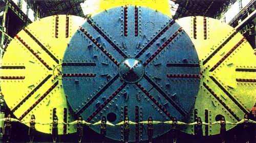
Fig.1: Mitsubishi Shield for a trinocular tunnel scheme.
Sprayed concrete (gunite) was invented and patented at the beginning of the twentieth century Allentown, PA, 1912 and was used for the first time in 1954 to stabilize and support squeezing ground in an eight (8) meter diameter diversion tunnel for an Austrian power plant (Mueller 1978, Sauer 1988). After a number of successful applications at water-, rail- and road tunnel projects, this method was adopted for the first time in urban areas in soft ground for a section of the Frankfurt Subway Scheme (Krimmer, Sauer 1985). This construction took place in Frankfurt clay in 1968. Because of its obvious flexibility, economy and safe performance, more than two thirds of Germany's mined urban mass transit tunneling sections in more than 10 major cities were carried out using this method by the mid 1970's. These tunnels were constructed in a variety of soft, mixed and hard formations such as: clay, silty clay, silt and soft marl, brittle to solid basalt and granite conditions.
For the performance of the work using shotcrete as initial support, only a few highly skilled miners and supervisors are required, while the majority of the mining crew can consist of locally recruited mining workforce. No major pre-investment is necessary and the excavation can start immediately after contract award. Its big disadvantage, the slower excavation rate (up to 3 - 7 meters per 24 hours in soft ground), can be compensated by increasing the number of excavation faces from additional shafts or adits (Heflin et al 1997). In the meantime, many large cities around the world, including Athens, Brasilia, Copenhagen, Dallas, Essen, Frankfurt, Geneva, Helsinki, Istanbul, Jerusalem, Kyoto, Lisbon, Madrid, Nürnberg, Ottawa, Quebec, Rome, Sao Paulo, Seattle, Seoul, Tokyo, Udine, Valparaiso, Washington, DC, Zurich, among many others, have taken advantage of this method.
Combined with compensation grouting, even old historic buildings in Lisbon (Schweiger, Falk 1998), London (Dimmock, Lackner 1997; Zeidler, Gall 1999), Vienna (Liebsch 1994) and elsewhere remained undisturbed while mining underneath them.
The NATM (New Austrian Tunneling Method) is said to be an observational method. (Peck 1969) Therefore, monitoring (in-situ measurements) of deformation in the ground and opening and stress development on and in the initial lining (shotcrete) is recommended. Any remedial work caused by violation of material specification, misalignment, other construction errors and errors due to unforeseen conditions must be carefully designed and follow the same step-by-step approach as adopted for the main design work.
GROUND IMPROVEMENTS AND ADDITIONAL SUPPORT MEANS
Face stabilization with earth wedge or shotcrete is standard today, as well as spiling in brittle and soft ground which recently has been used at many metro tunnels and some hundred tunnels of the high speed rail link in Germany. In even softer and sandy ground, however, grouted pipe spiling and grouting was and still is the state of the art solution.
Fig. 2: Ground improvement techniques used with NATM.
|
The under-passing of buildings or even vaults, like the one of the historic "Romer" or the "Hardy-Bank" in Frankfurt (Sauer 1998) required carefully grouted slabs in the Alluvium above the proposed tunnels. What has been developed in urban tunneling in the last thirty years is the "Ground Freezing" method. This concept has been successfully used on several projects, among them Zurich which is one of the most impressive ones with a cross-section of some 11 meters in diameter under multi-story buildings (Wind 1991).
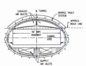
Horizontal jet-grouting has been developed in the last twenty-five years finding its way also into Singapore Metro (Buttling, Shirlaw 1988). Although the use of compressed air in underground tunneling is a proven technique for many years providing temporary support, it is now used in conjunction with shotcrete. Its economic success, however, remains at air pressures below 14 psi. (Weber 1983) The "Barrel Vault Method" (BVM) is one of the most cost effective methods to underpass railway or road embankments with a very high proven safety factor. This had already been demonstrated on many projects in Europe (Deinhard et al 1991), the United States (e.g. near San Francisco), as well as other locations in the past. |
A semi cut-and-cover method recently developed is the so called "Doorframe Slab Method" (DSM). Its advantages are the very temporary open cuts in busy streets (approximately 300 feet for one or two weeks at a time). During this period, the concrete slab is poured, spite side wall reinforcement is driven into the ground, and the surface is restored. (Fortner 1998, Negro 1998). After this, the underground excavation beneath the protective stab can commence.
Subdivision of cross-sections is a proven method to enhance safety in soft ground tunneling. This includes tunnels as shown at London Bridge in the UK (Zeidler et at 1997) or in a center-platform station in Bochum, Germany (Groves, Morgan 1997). Cross-sections in soft ground up to 65 feet springline diameter and more have been successfully built using side wall d rifts and subsequent widening to the full extension of the cross-section (Dressler 1990, Sauer 1990).
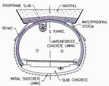
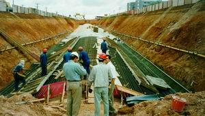
Fig.4: (a) Tunnel section using the DSM, (b) Construction of the Doorframe Slab at Brazilian Metro.
WATERPROOFING AND REHABILITATION
Based on its success, flexible waterproofing membranes are now being utilized for the waterproofing of underground structures in general. Concepts of waterproofing mined tunnels have been adapted to meet challenges of cut-and-cover construction methods including soldier piles and lagging, slurry walls, sheet piles and others (Mergelsberg et al 1996).
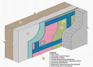
Fig.5: Waterproofing system and sectioning.
Similarly, rehabilitation projects of old, leaking tunnels see more and more use of flexible membranes. Operators of new and refurbished underground systems such as metros, road and utility tunnels and other subsurface structures such as libraries and parking garages are enjoying significantly reduced operation and maintenance costs as a consequence of dry underground space.
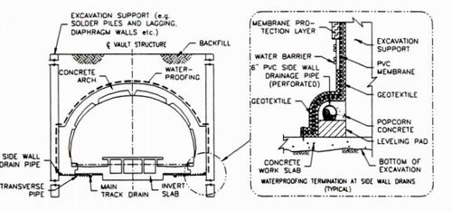
Fig.6: 'Open System' at Glenmont Station, Washington, D.C.
A system sketch for a typical waterproofing using flexible, continuous membranes is shown in Figure 5. This Figure also depicts an enhancement of the system by the so called `sectioning' for controlled repair by grouting. The waterproofing is applied in either the `open' or the `closed' system. The closed system allows the watertable to raise over the structure. The open system in contrast uses sidewall drains at invert elevation for permanent drainage of ground water (ground watertable below invert). Figure 6 shows a waterproofing section at Washington D.C. Metro's Glenmont Station.
AIRPORT ACCESS
|
Shotcrete as initial lining at mined airport access in combination with new techniques (BVM, DSM) have recently seen increased applications (Aldrian, Kattinger 1997).
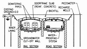
On the other hand, a modified Doorframe Slab (DFS) method has been recently proposed for an airport access by vehicular and rail traffic. This side by side, two lane / two track tunnel crosses beneath the airport's taxi-lanes in unstable, contaminated soils and under high groundwater levels. Under the proposed scheme, slurry walls would be placed, followed by excavation of a shallow trench to future roof level. Subsequently, a reinforced concrete slab would be cast, backfilled and airport traffic restored. As the work can be done in segments, parts of the runway could be open to traffic at all times. Under fully restored airport traffic, mining then can be done after sectional dewatering of the immediate excavation area while remotely recharging the outside area. Using multiple heading excavation closely followed by a structural invert to complete the structure (see Figure 7), a safe and competitive project is achieved. |
LONDON BRIDGE STATION
As part of the 16 km long Jubilee Line Extension London Underground Limited built the new London Bridge Station (Contract 104) between 1994 and 1999 (Way 1996).
The original construction design envisaged the use of hand mining methods and shield machines for excavation and segmental cast iron linings for tunnel support.
Hence after the successful completion of the Heathrow Trial Tunnel (Deane, Rulff 1992), an alternative approach was accepted that employed the principles of the NATM and combined them with other advanced accessory techniques such as Compensation Grouting.
Excavation of the station tunnels was carried out using backhoes and roadheaders and the tunnel support was established by reinforced shotcrete. For final support reinforced cast in place concrete and cast iron segmental linings were used.
Due to the location of the project in the center of London, it was focused on a smooth tunneling operation with minimal impact on the surface traffic and buildings. Also the Northern Line that is within the vicinity of the construction activities had to be kept operating without any disruption throughout the entire construction period, and virtually no deformations of the existing running tunnels could be accommodated, due to the tight clearance conditions within the existing Northern Line running tunnels.
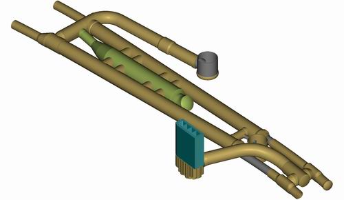
Fig.8: Isometric view of London Bridge Station comprising 11.5 m and 5.3 m Trail Tunnel, 1 Stepplate Junction (120 m²), 2 Stations, 1 Concourse Tunnel, 2 Escalator Tunnels, 2 Ventilation Tunnels and 3 Shafts.
The alternative method resulted in a satisfactory product and selecting the alternative construction method finally proved to be responsible and professional. Not only were geometrically very complicated tunnel alignments and shapes constructed with significantly lower effort, but also settlements were minimized which in turn reduced the financial effort for Compensation Grouting. Also, the overall construction cost for the parts of the scheme constructed using the NATM were significantly reduced. For example, the final construction cost for the bifurcation was only about one third of the construction cost estimated for the conventional method (Zeidler, Gall 1999).
MBTA - SOUTH BOSTON PIERS TRANSITWAY - RUSSIA WHARF SEGMENT The Russia Wharf Segment of the South Boston
Piers Transitway project crosses underneath the Russia Wharf properties. These properties comprise the Russia Building, Tufts Building and Graphic Arts Building, where the Tufts Building is located outside the tunnel alignment, The historically listed buildings were built approximately 120 years ago and are founded on timber pile groups. The building columns rest on pile caps consisting of granite blocks that are not interconnected. The clearance between the new transit tunnel roof and the pile caps varies from approximately 4.2 m to 1.8 m. The tunnels for he new transitway will accommodate bus traffic and, at a later stage possibly, light railway traffic.
The original design for the tunnel construction foresaw a box tunnel constructed within an open cut. The buildings which were located above the tunnels had to be evacuated, underpinned and the lower floors had to be stripped from all walls, floors and partitions to facilitate access for the excavation and support operation.
An alternative method was developed that allows the construction of the new transitway tunnels while Russia Building and Graphic Arts Building will remain in use as office buildings during the construction period (Fortner 1999). Only the basement floor, that is currently used as car park will be occupied by construction facilities and equipment.
The alternative method employs ground freezing to improve the ground around the tunnel roof area (fill material) such that the new tunnel can be mined essentially without disruption of surface or subsurface structures. For the initial tunnel support reinforced shotcrete will be utilized. The timber foundation piles of the buildings will rest in special pile shoes on the tunnel lining. For permanent waterproofing and tunnel lining a membrane waterproofing system and reinforced cast-in-place concrete lining will be installed.
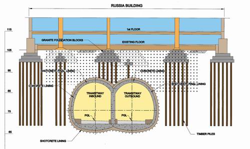
Fig.9: Schematic arrangement of tunnels, ground improvement and existing structures.
FLOOD MITIGATION AT BRUNEL'S THAMES TUNNEL
Brunel's Thames Tunnel is an approximately 400 m long brick lined tunnel and was built using a rectangular shield between 1825 and 1843. The tunnel connects the Thames river north bank with the south bank in London UK.
Two tunnels with horseshoe profiles were constructed within the bore. The twin tunnels are connected with a series of brick lined arches at approximately 5.5 m.
The prime objectives of the rehabilitation were: Strengthening of the structural support of the tunnel to ensure its integrity for the next hundred years including flood mitigation; additional clearance for an improved track alignment and larger rolling stock; modernization of electrical and safety equipment. British Heritage, the UK Authority for preservation of historic buildings, requested the preservation of all arches connecting the twin tunnels, a complex back-of- lining drainage and architectural features in the final lining similar to those generated by Brunel (Roach 1998).
To observe all these project aims and to ensures safety during rehabilitation operation, a series of excavation and support techniques were adopted (Wallis 1997). An `excavation' sequence was developed that allowed sections with limited lengths and depths for brick lining trimming according to the assessed brick lining conditions
and thicknesses. Temporary steel support frames and a comprehensive monitoring system was employed to ensure safety during the intermediate construction stages. Installation of the waterproofing/drainage system and the reinforced concrete or shotcrete final lining followed brickwork trimming in each individual trimming section. In March 1997 Brunel's Thames Tunnel was re-opened to the public.
BERRY STREET TUNNEL WIDENING
The brick lined Berry Street Tunnel in Pittsburgh, PA, was built in 1865 (Garrett 1997). The tunnel refurbishment commencing in April 1996 included the widening of approximately 710 m of mined tunnel and approximately 160 m of a cut&cover section at the north-east end of the tunnel (Gall et al 1998).
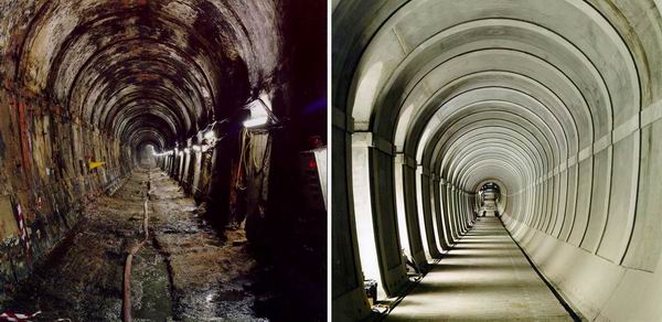
Fig.10: Brunel's Thames Tunnel prior to and after refurbishment.
The main part of the tunnel was widened using steel fiber reinforced shotcrete for initial support. The cut&cover section at the north east end of the project was widened partially using mining techniques as far as practical. Where the backfill cover above the tunnel became too shallow the method was changed to cut&cover techniques and a shotcrete canopy was installed in the open cut. Also the 152 m long extension of the tunnel was constructed using a shotcrete canopy. The shotcrete canopy was backfilled with adequate material prior to waterproofing and concrete lining installation. This approach accelerated the construction process and limited construction costs, since extensive support of the slopes alongside the cut&cover section was made redundant and excavation of old backfill and rebackfill was eliminated over a considerable tunnel length. The same steel form shutter for the concrete lining installation was used for the mined section and the cut&cover section (Whitley 1998).
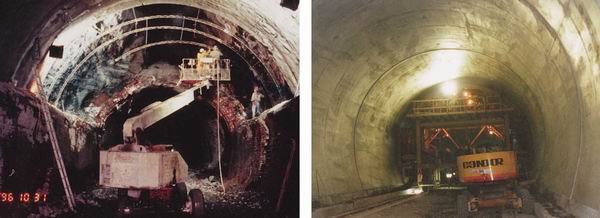
Fig.11 (a): Shotcrete canopy installation under voids, (b): Final tunnel lining.
After installation of a waterproofing system the unreinforced cast-in-place concrete lining was installed. Tunnel refurbishment work was completed in August 1997. The success of the project was a consequence of the flexible design approach selected. Modern support measures required for the expected ground conditions were thoroughly designed and prepared providing various tools to be utilized in varying combinations and adaptions to overcome the problems encountered.
CONCLUSION
To construct miscellaneous underground structures in urban underground as challenged by the vast amount of upcoming Transit projects, (O'Neill 1999) there are a variety of advanced, improved and new construction elements and methods available today. Short underground bores, especially twin tunnels with underground branches, mined stations, cross-over chambers, shafts, escalator tunnels, caverns and widenings along tunnels and other auxiliary space which needs to be mined, require an easy to handle, flexible construction technique, that can cost effectively adapt to irregular geometries and unforeseen conditions.
It can be used in virtually any kind of ground conditions given the variety of ground improvement means available today provided there is a proper design and skillful contractors as well as responsible and experienced supervision (Terzaghi 1998). This shotcrete tunneling or sequential support technique has also successfully been applied in the rehabilitation of underground structures. The neither "New" nor "Austrian" Tunneling Method `NATM' has proven worldwide to be one of the most adaptable and responsive excavation and support methods at economic cost for such purposes.
REFERENCES
Aldrian, W., Kattinger, A. (1997): Monitoring of performance of primary support of NATM station at Heathrow Terminal 4. Proceedings, World Tunnel Congress Vienna 97, 71-77
Buttling, S., Shirlaw, J. N. (1988): Review of ground treatment carried out for tunnels of the Singapore Mass Rapid Transit System. Proceedings, Tunnelling 88, April 1988, London, England, 39p
Deinhard, M., Prinz, H., Zeidler, K. (1991): Variations on an NATM theme. Tunnels & Tunnelling, November 1991, 49-51
Deane, A., Rulff, J. (1992) : Heathrow Express - NATM Trial Tunnel. World Tunnelling, June 1992, Volume 5, 242-246
Dimmock, R., Lackner, J. (1997): A unique NATM solution for the London Underground. Proceedings, International Tunnelling Conference: Tunnelling in difficult conditions, Basel, Switzerland, 1997, 261272
Dressier, J. (1990): Design and construction of a shallow underground parking cavern in soft ground. Proceedings VoL 1, International Symposium on Unique Underground Structures '90, Denver, Colorado, USA, Chapter 17, 1-17
Fortner, B. (1998): New method opens door to easier tunneling. Civil Engineering, October 1998, Vol, 69, No 3,34-39
Fortner, B. (1999): Through Frozen Ground. Civil Engineering, March 1999, Vol, 68, No 10,16
Gall, V., Zeidler, K., Predis, T., Walter, J. (1998): Rehabilitation Concepts for brick lined tunnels in urban areas. Proceedings, World Tunnel Congress '98 on Tunnels and Metropolises, Sao Paulo, Brazil, 539-546
Garrett, R. (1997): Pittsburgh Berry Street Rebuild. North American Tunneling, June 1997 Issue
Groves, P. N., Morgan, S. R. (1997): Engineering consequences of ground conditions on NATM works. Proceedings, Tunnelling '97, Institution of Mining and Metallurgy, London, 677-692
Heflin, L. H. , Marquardt, J. M., Yen, J . H. N. (1997): Eight Heading Rock NATM. Proceedings, RETC, Las Vegas, 1997, Chapter 38, 625-630
Krimmer, H., Sauer, G. (1985): Die Neue Österreichische Tunnelbauweise im UBahnbau Rückblick und Ausblick. Österreichische Gesellschaft fuer Geomechanik, Felsbau 3, Nr. 3
Liebsch, H (1994): Verfahren zur Begrenzung von Setzungen beim Herstellen unterirdischer Holraume. Europäische Patentschrift, Veroffentlichungsnummer 0 498 786 B1, 1994
Mergelsberg, W, Gall V., Sauer, G. (1996): Achieving dry Cut-and-Cover Stations - A membrane based waterproofing system for underground structures. Proceedings, North American Tunneling '96, Vol, 1, Washington, DC, USA, 353-361
Muller, L. (1978): Der Felsbau, dritter Band: Tunnelbau. Ferdinand Enke Verlag, Stuttgart, Germany, 945p
Muir Wood A M. (1979): Ground behaviour and support for mining and tunnelling. 14th Sir Julius Wernher Memorial lecture '79, A23-34
Munfah, N.A., S. Zlatanic (1998): Design Considerations of a turnkey contract for an underground LRT system. Proceedings, Tunnels and Metropolises, 1998, Sao Paulo, Brazil, 129-134
Negro, A. Jr. (1998): Brasilia Metro Underground. ASCE Convention, Boston, MA, USA
O'Neill, T. J. (1999): Transit Trends in the United States Proceedings, International Conference on Rail Transit, 1999, Singapore
Peck, R. B. (1969): Deep excavation and tunneling in soft ground. Proceedings 7' International conference on soil mechanics and foundation engineering; state of the art volume, Mexico City, Mexico, 225-90
Roach, M.,J. (1998): The strengthening of Brunel's Thames Tunnel. Instn. Civ.Engrs., Transp. 1998, 129, 106-115
Sauer, G. (1988): When an invention is something new: from practice to theory in tunnelling. XXIII Sir Julius Wernher Memorial Lecture, Institution of Mining and Metallurgy, Tunneling '88 Symposium, London, UK, A94A108
Sauer, G. (1990): Design concept for large underground openings in soft ground using the NATM. Proceedings Vol. 1, International Symposium on Unique Underground Structures '90, Denver, Colorado, USA, Chapter 1, 1-20
Sauer, G. (1998): Shallow tunneling in urban areas. Urban Geotechnology and Rehabilitation Seminar sponsored by ASCE 1998, New York, 130-141
Schweiger, H.F., Falk, E. (1998): Reduction of settlements by compensation grouting - Numerical studies and experience from Lisbon underground. Proceedings, Tunnels and Metropolises, 1998, Sao Paulo, Brazil, 1047-1052
Terzaghi, K. (1958, 1998): Consultants, Clients & Contractors. BSCE Journal 1/1958 (reprinted at Civil Engineering Practice Fall/Winter 1998), Boston, MA, USA, 46-54
Wallis, S. (1997): The Thames Tunnel. Their finest hour NATM, September 1997, 38f
Way, A (1996): JLE Contract 104: all change at London Bridge. Tunnels and Tunnelling, November 1996, Vol. 28, No 11, 52-56
Weber, J. (1983): Erfahrungen mit Druckluftvortrieben in Spritzbetonbauweise beim Münchner U-Bahn-Bau. Unterirdisches Bauen, Technik und Wirtschaftlichkeit, Stuva-Tagung 1983, Nürnberg, Germany, 58 p
Whitley, T. (Ed.) (1998): The Austrian way. International Construction, March 1998, Vol, 37, No 3, 41-44
Wind, H. (1991): Soil and Rock improvement in underground works - site organization of ground freezing, criteria and recommendations. ATTI Proceedings, Vol. II, March 1991, Milano, Italy
Zeidler, K., Groves, P., Sharrocks, D., Allen, R. (1997): Surface settlement due to the construction of the London Bridge Station Tunnels by NATM. Proceedings, World Tunnel Conference '97 on Tunnels for People, Vienna, Austria, 429434
Zeidler, K., Gall, V. (1999): Shotcrete lining design concepts for new and rehabilitated tunnels. Proceedings, United Engineering Foundation Conference 1999 Shotcrete for Underground Support, Sao Paulo, Brazil