You are here
Engineering a longer Life for Brunel's Tunnel
August 26, 1998
London, United Kingdom
Engineering a longer Life for Brunel's Tunnel
Refurbishment of the East London Line - Thames Tunnel
Dr. G. Sauer Company
Railway Strategies - For Senior Rail Management, January-February 2003
The rehabilitation of Marc Brunel's Thames Tunnel was undertaken over a 24 month period by Atkins and Dr. G. Sauer Company Ltd. (DSC) acting as a specialist tunneling, shotcrete and waterproofing consultant, with the contract novated to Taylor Woodrow Civil Engineering Ltd. (TWCE).
|
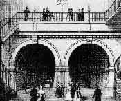
INTRODUCTION The Thames Tunnel was constructed by Marc Brunel between 1825 and 1843 and was the world's first bored tunnel crossing of a river as well as the first example of a shield driven tunnel. The approximately 400m long structure runs between Wapping on the north bank of the River Thames and Rotherhithe on the south bank in east London. Originally designed for horse and foot traffic, the tunnel now forms part of London Underground Limited's (LUL) system. Refurbishment was aimed primarily at strengthening the tunnel by the construction of a new lining inside each of its twin bores to accommodate the passage of LUL's vehicles with appropriate clearances for the dynamic envelope of the carriages and the services to be contained within the tunnel. THE TUNNEL STRUCTURE The brick tunnel structure has a rectangular outer profile and twin side-by-side horseshoe inner tunnel profiles linked horizontally by brick lined arches at approximately 5.5 metre centres. The arches were cut out of the inner wall separating the two bores after the tunnel had been completed. The structure is located at very shallow depth below the bed of the River Thames over much of its length and is situated mostly in the alluvial deposits of the river Thames (Themes Gravel) and strata of the Woolwich and Reading Beds. |
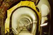
Figure 1: Brunel's Thames Tunnel more than 150 years after opening
|
The tunnel was constructed from mortared brickwork using a shield which comprised twelve vertical side-by-side cast iron frames, each with three compartments. Each frame was advanced separately by the use of screw jacks acting against the brickwork which was built close behind the shield. The twin bores were lined with terra cotta tiles which were fixed generally on 'dentition'brickwork protruding from the structural brick lining. The inner profiles of the structural brick to the bores were irregular and the tiling so fixed off the dentition brickwork afforded the means of producing a relatively uniform internal profile circumferentially and longitudinally and also provided a mechanism for constraining any groundwater which leaked into the tunnels and channelling it to invert level. In some places, due to misalignment of the inner structural brick profile, tiles were fixed directly onto the structural brick and drainage grooves were 'chased' into the structural brick to maintain the capability of containing any leakage into the tunnels. Water inflow ran down to dip sumps located near the lowest point in the tunnels from where it was pumped to the surface.
|
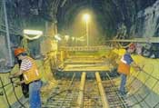
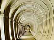
Figure 2: Invert concrete under preparation. Reinforcement steel,
|
THE REFURBISHMENT SCHEME The Dr.G. Sauer Company (DSC) was originally commissioned by LUL to undertake the design of the new lining to the twin bores. The commission was subsequently novated to Taylor Woodrow Civil Engineering Ltd (TWCE) when they were appointed main contractor for the works. However, in April 1995, the structure gained Grade II* Listed status and it then became a requirement that the four cross passages at the southern (Rotherhithe) end of the alignment and the two bores with their tiled finish over this length be retained as a 'Preserved Section'. Subsequently, further constraints were placed on LUL by third parties and the refurbishment scheme finally implemented involved:
DESIGN CONSIDERATIONS AND REQUIREMENTS Although the broad principles to be adopted for the design of the tunnel linings were available, specific details for the refurbishment scheme finally adopted were only resolved during the design process through a 'Design Panel' comprising representatives from LUL,TWCE and DSC. This procedure was necessary to accommodate specific requirements arising from the 'Listed' nature of the structure and also the fact that only very limited reliable information was available regarding the nature and spatial location of the structural brickwork since much of the tiling to the tunnels was still in place. Consequently, as and when the tiles and dentition brickwork were removed and structural brick survey data became available, changes or amendments were made to the design (particularly to the profile and vertical alignment) to accommodate the survey information, specifically in relation to a requirement to minimize structural brick removal. |
The design requirements essentially included, but were not limited to -
-
Minimizing the permanent tunnel lining thickness to accommodate restrictions imposed by the required structure gauge envelope whilst aiming at the same time to restrict the removal or trimming of structural brickwork. The target minimum thickness of remaining brickwork was 675mm whilst the target minimum thickness of lining was 200mm to be constructed from a minimum C40 concrete with conventional steel bar and steel fibre reinforcement. The invert to the lining and the track slab for the rails were designed as a composite structure to minimize lining thickness and brickwork removal in the invert;
- Basing the horizontal and vertical alignments on the existing alignments to fulfill as far as practicable permanent way requirements and further minimize the amount of structural brickwork to be removed to form the new lining;
- Incorporating a waterproof membrane with a geotextile fleece around the periphery of the tunnels above invert level between the permanent lining and the existing brickwork. Notwithstanding this-requirement, the design was to incorporate a 'back-of-lining' drainage system
-
Designing the permanent lining to Limit State Design in accordance with BS 8110 Part 1:1985 taking account of the maximum live and dynamic track loadings. The lining was required to withstand the full loading imposed by the soil (including the existing brick lining which was not to contribute to the support), surface structures, permanent way structures, services and the full hydrostatic loading generated by groundwater and the river at its maximum tidal level.
During the design process, four revisions to the permanent lining profile and three revisions to the vertical alignment were made in the light of further and better information being obtained in relation to the existing brickwork.
STRUCTURAL ANALYSIS AND DESIGN
Analysis of the tunnel lining was carried out using 2 dimensional Finite Element methods. Provision was made for three dimensional analysis in view of the presence of the cross passages but in the event this was deemed not to be necessary.
Seven load cases were considered to cover various long term loading conditions on the inner lining at the lowest point in the tunnel. A design requirement was the assumption that the brickwork had deteriorated to a granular material with time.
The design ultimately involved 200mm thick concrete linings for both the tunnel bores and the cross passages, reinforced with two layers of welded wire fabric and incorporating steel fibres. No allowance was made in the lining design for the steel fibres in terms of their potential contribution to the structural capacity of the linings but they were acknowledged in respect of their beneficial influence on early thermal cracking.
The design incorporated a waterproof membrane (backed by a geotextile fleece) behind the linings in both the tunnel bores and the cross passages. The 'back-of-lining' drainage system was also incorporated in the design such that any water emanating from the brickwork would be allowed to drain through the lining into lateral half-round drains formed in the track slab. These drains discharged into rodding pits formed at regular intervals in the track slab, the water then flowed through drainage pipework cast in the track slab, eventually discharging into the dip sumps at the lowest points in the twin bores.
CONSTRUCTION
The original intent was to construct the inner linings to the bores and the cross passages using sprayed concrete. In the event, TWCE elected to cast the inner linings to the tunnel bores and the cross passages using specially fabricated steel shutters. Sprayed concrete was used to form the linings to the two bores at the northern (Wapping) end of the alignment over a length of approximately 18m because of the complex intrados geometry resulting from the fact that the tunnel was on a horizontal transition curve and the requirement to tie-in with the existing portal structure.
Following construction of the track slab throughout both bores and the reconstruction of the dip sumps, the cross passages were relined using a steel shutter. The shutter was designed so that particular architectural features required to be incorporated in the final structure could be replicated at the time of casting the lining.
Lining of the twin bores commenced only when all the cross passages had been relined to provide pre-support in view of the subsequent requirement to remove structural brickwork to varying degrees prior to casting the lining to the twin bores. The 5.5m long shutter for the main tunnel linings was in modular form such that it could be shortened as necessary in areas where significant amounts of structural brickwork had to be removed to limit the length of tunnel so affected.
Monitoring in the main tunnels during brickwork removal included tape convergence measurements and load and deformation measurements using temporary steel frames. The frames, which were jacked against the brickwork, were fitted with load cells and strain gauges which were continuously monitored through a computer controlled system.
Construction was successfully completed in the Spring of 1997.