You are here
Pittsburgh Berry Street Rebuild
Pittsburgh Berry Street Rebuild
WT No.5 1997
World Tunnelling V.10, No.5, June 1997
The reconstruction of tunnels may afford the opportunity to significantly enlarge the tunnel dimensions.
The Port Authority of Allegheny County, Pittsburgh, Pennsylvania, is very pleased with its Berry Street Tunnel reconstruction results. The authority benefited from the contractor's original low bid and its post-bid tunnel-design change. The original bid was almost US$ 3 million lower than the nearest competitor, a fair proportion for a project costing under US$ 40 million.
However, that was only the start of the savings to come. The contractor, Mosites Construction Company of Pittsburgh, PA proposed a tunnel-design change to the authority immediately after being awarded the contract. This was contingent on the valued engineered idea, whereby owner and contractor share any project cost reduction.
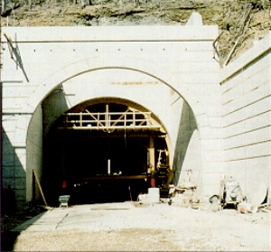
Berry Street portal with concrete formwork in position.
Mosites has an excellent reputation in the tri-state area of Pennsylvania, West Virginia and Ohio as a heavy construction and commercial building contractor. However, this was their first attempt at major tunnel construction so, to pre-qualify for bidding the project, the company established a business relationship with the Dr G. Sauer Corporation of Herndon, VA. Sauer is a consulting tunnel- construction engineering firm with extensive experience in NATM tunnelling worldwide. Tom Predis, project manager for Mosites, says Sauer not only enabled his company to pre-qualify for the project but gives Sauer VP Vojtech Gall credit in obtaining approval for the NATM method.
PROJECT BACKGROUND
The project calls for widening the tunnel to 30.5 ft. The original tunnel was built in 1865 (then called the Cork Run tunnel) as a 12 ft- wide, single-track rail tunnel. It was widened in 1873 to 25 ft. double-track with a 26 in- thick, brick-lined horseshoe design.
Full title of the project is the Airport Busway/Wabash Tunnel HOV Facility, Berry Street Tunnel and calls for the reconstruction, widening and extension of the 2,900 ft tunnel and the construction of the approach roadways with appurtenance structures. When completed, the tunnel will feature dual roadways, lighting, ventilation, fire protection and a sophisticated drainage system. It will be a link in the Airport Busway for both local and express buses en route between the Borough of Ingram, at the south portal, and Pittsburgh's Sheraden section at the north portal.
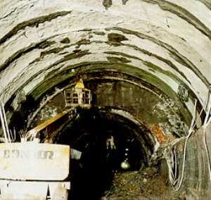
Erecting Pantex lattice girders as the existing tunnel section is enlarged.
Jim Walter, Civil Engineering Manager for the Port Authority, says the original tunnel reconstruction design made by Michael Baker Jr. Inc and ICF Kaiser Engineering was sound. He explains, "We are very conservative when designing projects such as this. Two main considerations of which Kaiser was mindful were: safety for the tunnel workers, and elimination of overbreak during excavation. Also, no blasting was to be used. Kaiser's tunnel design met these parameters."
Unlike some public agencies, the forward thinking Port Authority is receptive to valued engineering (VE) proposals made by contractors. Walter says if a VE proposal can meet the original construction parameters and result in significant cost reductions, it will be accepted. Important construction parameters for this project included: high safety standards during its construction, extensive overbreak containment and conservative structural-integrity standards.
The Sauer-proposed NATM design met or exceeded the parameters. The cost reduction came to US$ 2 million dollars and included the revised tunnel design, some retainer wall construction changes at the portal and the elimination of a cut and cover segment in favour of the NATM method.
NATM BENEFITS
At a series of meetings Vojtech Gall outlined to the owner the benefits in using the NATM method: the initial support system used is flexible and dependent on the changing ground conditions; NATM takes advantage of the in situ ground conditions by means of ground self-support; the tunnel alignment was to be elevated two to four feet, putting the crown in better ground conditions and reducing presupport and support requirements; and, most compelling of all, there were substantial cost savings to be realized.
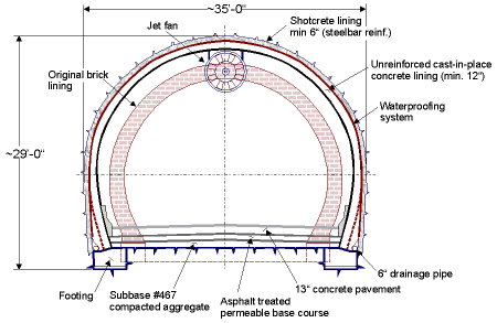
Typical cross section geometry
The original excavation method called for first drilling a designated pattern of groutinjection holes into the tunnel's existing crown and sides. Cementitious grout was to be used as consolidation grout to fill all voids between the brick liner and the ground. It also was to fill rock delaminations and fissures present, up to 20 ft deep.
The joints to be filled are along the bedding planes above the crown. Also, the existing backfill behind the liner was to be grouted to assure superior rock-dowel performance.
With the grout and rock dowels in place, excavation was to be carried out using a road header and supported by lattice steel girders (spaced three to four feet), steel spiring and shotcrete.
Installation of a waterproofing membrane followed by a 15 in-thick, cast-in-place, final reinforced concrete liner would complete the basic construction of the straight-wall design.
With the final liner installed, contact grouting was to be used for filling any voids between the newly cast-in-place concrete liner and the shotcrete liner. The function of the contact grout was to bond the liner's entire surface to the shotcrete (especially at the crown), thus distributing stresses without significant deformation.
The NATM design eliminated drilling 20,000 grout-injection and rock-dowel holes. In turn, that eliminated installing 10,000, 20 ft-long rock dowels and injecting 200,000 bags of grout. Two other cost-saving ideas were the reduction of the final liner design thickness from 15 in to 12 in and eliminating its rebar.
EXPERT TEAM
Mosites depended on expert information from different sources to launch the project. Tom Predis describes his approach to materials suppliers: "I wanted more than competitively priced products. I wanted companies that could give us expert advice on implementing their products on this project. That eliminated many competitors up front."
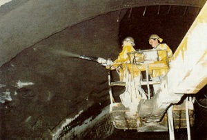
Shotcreting for support
American Commercial Inc. of Louisville, Kentucky, through its regional manager David Klug, supplied a Pantex girder type 50/6/8 that was lighter and less expensive than the one originally specified but met the girder-design parameters specified by Sauer for their NATM design. Placing the tunnel crown in sounder ground conditions reduced loading on the lattice girder support system and allowed thinner shotcrete. The tunnel's vertical dimensions were held in the Sauer design with the girders installed in a modified horseshoe profile instead of the original straight-wall design.
Master Builders Technologies, Inc. (MBT) of Cleveland, OH played a very important role on this project by contributing far more than its concrete/shotcrete admixture products. MBT people offered expertise in designing the shotcrete mix to meet specifications, batch mixing the shotcrete and applying it.
George Yoggy, director of the Underground Systems Division, trained the contractor's new shotcrete crews in the art of spraying.
Yoggy is considered by many contractors as amongst the most knowledgeable people in shotcrete application, one of many reasons that MBT got the admixture business. Predis explains: "I met with MBT people and other qualified competitors before awarding the admixture business to them. My conclusion was MBT could supply superior service plus expert knowledge on shotcrete mixing at our mix plant and application at the gun." MBT helped the contractor to select the right shot crete mixer configuration for the job and made up the shotcrete-mix design at their Cleveland laboratory.
Elfin Manufacturing Company of Indiana, PA supplied an Elfin Hitch stationary-mixer, shotcrete mix plant with a maximum mixing capacity, as used at this project, was 18 yd3/hr based on repetitively mixing 6 yd3 batches of shotcrete.
Predis says mixing their own shotcrete was driven by economics. With shotcrete deliveries required around the clock, the contractor would have had to pay premium prices to a ready-mix company because of additional production shifts.
The shotcrete mix-design calls for a high quantity of steel fibres to ensure residual, high flexural strength. The same mix has been used successfully on other tunnel projects and the alternative would be to add fewer fibres and monitor the toughness properties using the expensive ASTM 1018 test procedure.
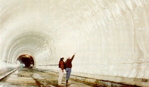
Waterproofing membrane in place prior to final lining.
GROUND CLASSIFICATION
The geology along the tunnel alignment includes claystone, siltstone, sandstone, coal and shale. The NATM ground-behaviour- classifications made by Sauer were categorized by four classes and subsequently modified for the valued engineering construction procedure. The reclassification was a much more conservative approach designated as contingency ground classes with suitable support types. There were three classes and four types as described:
Class SW Portal:
Minor afterbreak and shallow cover above the tunnel crown. Systematic rebar spiring; lattice girders on 40 in centres; maximum round length: 4 ft top heading, 8 ft bench.
SW-Portal Contingency type: Systematic grouted-pipe prespiling; lattice girders on 40 in centres; maximum round length: 4 ft top heading, 8 ft bench.
Class I:
Stable ground with minor aherbreak decreasing significantly with time. Rebar prespiling as required; pattern rockbolt installation; lattice girders as required; maximum round length: 8 ft top heading, 16 ft bench.
Contingency type A: Fairly stable ground with minor to moderate afterbreak Rebar prespiling as required; pattern rockbolt installation; lattice girders 5 ft on centre; maximum round length: 6 ft top heading, 12 ft bench.
Contingency type B: Blocky ground with voids above the brickliner. Significant afterbreak and overbreak. Systematic rebar spiring; pattern rockbolt installation; lattice girders 6 ft 8 in on centre; maximum round length: 8 ft top heading, 16 ft bench.
Class II:
Stable blocky ground with significant voids over the brick liner, minor afterbreak and overbreak. Rebar prespiling as required; pattern rockbolt installation; lattice girders as required; maximum round length: 8 ft top heading, 16 ft bench. A shotcrete canopy built under large voids and before backfilling.
Contingency type D: Blocky ground with large voids over the brick liner and significant afterbreak and overbreak. Systematic rebar prespiling installation; pattern rockbolt installation; lattice girders 6 ft 8 in on centre; maximum round length: 8 ft top heading, 16 ft bench. Shotcrete canopy built under large voids before backfilling.
Once the initial support system was installed, a 1 in smooth coat of unreinforced shotcrete was applied. A waterproof membrane is now being installed by Wisko America Inc of Kensington, MD followed by the contractor casting in place the final concrete liner.
SUMMARY
The productivity was acceptable to the contractor, considering the learning curve required to train the tunnellers. Crews averaged 15.1 ft/24 h day working from both ends.
There is a popular misconception in North America that all NATM tunnels are more expensive than conventionally built ones, but that is certainly not true here. The major benefit to the owner has been a significant cost saving without compromising construction quality or reducing safety standards.
The owner had the foresight and willingness to change the tunnel construction design. However, the same agency commissioned the Mt Lebanon twin NATM tunnels in 1985, so are not strangers to the technique.
Though not an expert in tunnelling, the contractor was willing to build the tunnel using the NATM design. The risk was carefully calculated and based on their confidence in Sauer's NATM tunnel-design expertise and construction management experience and the handful of companies who helped carry out many of the NATM procedures. Using the valued engineering approach the contractor and the owner were, of course, monetarily well rewarded.
ACKNOWLEDGEMENTS
My appreciation to Tom Predis, Mosites; Jim Walter, Port Authority of Allegheny; David Klug, American Commercial; George Yoggy, Master Builders Technologies and Vojtech Gall, Dr. G. Sauer Corporation. They were very helpful in putting this report together. Contact fax +1 610 488 9232.