You are here
GSA Loose Rock Anchor Bolts
GSA Loose Rock Anchor Bolts
Tunnel 3/89
Tunnel Magazine, Volume 3/89
GSA Loose Rock Anchor Bolts
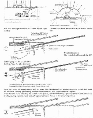
When working with anchor bolts in loose rock (gravel, sand, schluff, clay, rnylonitised fault zones, etc.), there is the danger that the borehole caves in again between the creation of the hole and the setting of the anchor bolt. The GSA eliminates this disadvantage in that the anchor bolt is flushed out of the drilling rod with the help of the grouting material while this is being retracted.
The anchor bolt itself can be made of steel, plastic, fibre glass, etc. The grouting material can be mortar, synthetic resin, on a water-glass basis or something similar.
The anchoring process takes place as follows - as can be seen frown the drawings:
-
 Directly after excavation, the face and the wall are secured by means of sealing shotcrete. By closing the pores, the material is prevented from softening through hydrophiles and any initial movement is stopped. Subsequently, the anchor bolts are set using a conventional jumbo equipped with a special drilling rod, mixing valve and pump aggregates. The number and density of the anchor bolts or lances depends on the prevailing rock conditions.
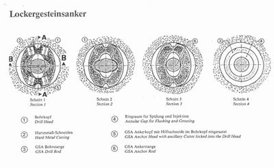
 - Once the anchor bolt has been set, the rod is again flushed and loaded with a new anchor piece front the front or rear depending on the type of drill hammer (by unscrewing the rod). The anchor piece is secured in the drill head by turning it by 90° - and locking it into place (in the case of loading from the rear).
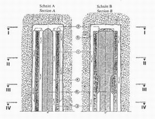
- The drilling phase takes place - depending on the type of rock - with water or air flushing. The flushing flows through the annular gap between the anchor rod and the drill rod into the drill head. Two apertures are installed in the drill head to allow the flushing fluid to escape.
Roughly half a metre before reaching the end of the borehole, the grouting phase is commenced so that the injected Material has reached the drill head once the end of the borehole has been reached. During retraction, the withdrawal speed is correlated with the amount injected in such a way that some 10 to 30 % more is grouted than corresponds to the theoretical volume. The grouting pressure amounts to between 10 and 20 bar; depending on the nature of the rock. Flushing is resumed half a metre before the end of the withdrawal phase so that once the drill rod has been completely retracted, the flushing has reached the drill head.
It should be printed out that this system not only ensures the secure installation of anchor pieces but also safe corrosion protection thanks to the complete enclosure of the rod with the grouted material.
In addition, this method can also be applied wihout anchor piece providing the drill head is slightly modified (the aperture has to be diminished). In this case, the borehole is only filled with grouting material. This is e.g. necessary and advisable for securing the face itself or supporting in subsequent drivage zones, where the rock material is subsequently removed.
|
|
PUBLICATIONS
Reuther, E.V., Manual of the Science of Mining, Volume I, 11th completely revised Edition, 832 Pp, 552 Ills., Verlag Gluckauf GmbH, Essen, 1989

