You are here
The Doorframe Slab Method, Barrel Vault Method and Conventional NATM
Rapid Excavation and Tunneling Conference, June 13-17, 1993
ABSTRACT
The road by-pass at Oberrieden, a small town near Gottingen, Germany, was built to relieve the small city's congestion of the daily through traffic. After the German reunification, the by-pass has become a major artery between the formerly separated states.
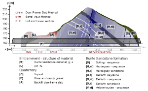
The construction of a 520 m long two lane road tunnel demanded tunneling through soft ground with shallow overburden and through a 120 year old man-made embankment (40% porosity) under an operating railroad. The state-of-the-art tunneling techniques that were utilized were the Doorframe Slab Method in sandy material as an alternative to regular cut-and-cover construction and the Barrel Vault Method for tunneling through the embankment.
INTRODUCTION
In the process of improving the road B 27 between the cities of Göttingen and Fulda (Hessen, Germany), it became necessary to build a by-pass for the town of Oberrieden. A particular challenge of the by-pass alignment was the crossing of a railroad embankment. The German Federal Railway imposed the requirement that the rail tracks had to remain open throughout the by-pass construction and without any speed restrictions to rail traffic. At early design stages, the options for the rail crossing comprised a viaduct, a road bridge and a jack tunnel alternative but were ruled out.
A final assessment of environmental, geologic and traffic conditions called for a 520 m long tunnel section. This tunnel section approaches from the south passing through the Schürzeberg, a hill bordered by the Werra river, leading to a cutting and subsequently passing at an angle through the railroad embankment, the German Federal Railway`s 120 year old Schürzeberg tunnel is located to the west of the road tunnel. Work on this tunnel project started in July 1990. The tunnel was opened to traffic in September 1992.
PROJECT DESCRIPTION
The alignment has a radius of 500 m in plan and a grade of 0,8% from north to south. The clearance envelope encompasses two lanes each 3.75 m wide, with two curbs of 0.25 m width and two 1.0 m wide walkways. The vertical clearance measured from road surface is 4.5 m. This results in atotal clearance envelope area for the traffic of 60 m2. The tunnel is designed as a twin structure comprising a reinforced initial shotcrete lining and a cast-in-place inner concrete lining. A waterproofing system, featuring a 2 mm PE plastic membrane and non-woven geotextile is installed between the initial and inner linings. The total excavated area of the crosssection, is approximately 100 m2. The inner cast-in-place concrete lining, completely covered with a washable synthetic resin based coating with reflecting color along the entire inside perimeter, represents the final finish of the tunnel interior. The tunnel is equipped with approach and transit lighting and all typical road tunnel safety installations. For ventilation, the longitudinal system has been selected using 2 booster fans. The fully automated central control room is located at the north portal.
GEOLOGY
Schürzeberg
The Schürzeberg comprises rocks from the middle bunter sandstone period, mainly thick-bedded to platy hard sandstones and clay stones. The rock refraction (Hercynina and Rheinisch direction) is limited to thin faults with small fillings, shears and entrainments. Major masses of detritus and wastage flank the Schürzeberg. The presence of groundwater is restricted to dripping water .
The Northern Slope of the Schürzeberg up to the Railroad Embankment
This section comprises mainly young, fluvial slightly silty fine sand with some gravel. Site investigations indicated the presence of groundwater with levels of approximately 6 m below tunnel invert.
The Embankment
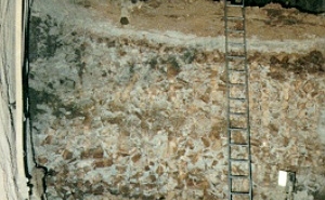
The major portion of drivage through the railroad embankment took place through manmade fill consisting of broken sandstone, the waste material from the excavation of the old railroad tunnel and used to construct the embankment. Loosely dumped rock material with edge lengths of up to 40 cm and void rations of up to approximately 40%, cohesivestona clay and very fine graines, soft clays resulted in an extremely inhomogeneous structure. Fluvial, very fine grained, non-cohesive sands were encountered at the base of the embankment.
CONSTRUCTION METHODS
NATM (Length = 372 m)
Regular NATM (New Austrian Tunneling Method) excavation using drill-and-blast was used to complete the tunnel section through the sandstones of the Schürzeberg from north to south. The basic initial tunnel support comprised a 20 to 30 cm thick shotcrete layer reinforced with either one or two layers of welded wire fabric (wwf) and lattice girders complemented by systematic rock bolting using fully grouted rock bolts of 4 to 6 m in length.
Four different ground support classes were defined for the changing ground conditions. The support classes are detailed as follows:
Support Class I: 20 cm shotcrete, 1 layer wwf, length of advance 1.35 to 1.75 m.
Support Class II: 30 cm shotcrete, 2 layers wwf, 4 rock bolts (1= 4m), length of advance 1.25 to 1.35 m.
Support Class III: 30 cm shotcrete, 2 layers wwf, 6 rock bolts (1= 5m) and 4 rock bolts (1= 6m) length of advance 1.0 to 1.25 m.
Support Class IV: 35 cm shotcrete, 2 layers wwf, 6 rock bolts (1= 6m) length of advance 0.75 to 1.0 m.
The excavation cross section was subdivided into top heading (H = 6.15 m), bench (H = 2.10 m) and invert (H = 1.50 m ) drifts.
The strata layers, dipping against the tunnelling direction in connection with numerous fissures, small and medium joints, resulted in rock blocks with the tendency to slide into the opening at the tunnel face. For this purpose, face supporting rock wedges were left in place during excavation. To prevent loosening of blocks and the roof area, spilling was employed as required. During tunnel drivage through the Schürzeberg, no significant problems were encountered which is mainly due to the lack of groundwater inflow and the rather competent coherence of the blocky rock mass.
The maximum settlements in the roof were measured to be 17 mm, and the maximum horizontal deformations were 14 mm. The average daily advance rate of top heading excavation amounted to 4.4 m/day.
Doorframe Slab Method (Length = 41 m)
The section between mined tunnelling and application of the Barrel Vault Method was initially planned to be carried out by the use of regular cut-and-cover construction. This would have, however, required movement of large amounts of earth and construction of heavy bore piled restaining walls with tie backs along one side, and therefore would have been a rather expensive undertaking.
A cost saving approach was selected using the Doorframe Slab Method, a patented construction technique by the Dr. G. Sauer Corporation. This method has been initially developed for tunnel construction in urban areas where the ground cover is too shallow for mined tunnelling, and regular cut-and-cover constructions creates major problems for traffic, utilities and adjacent structures.
The Doorframe Slab Method is a modified cut-and-cover technique which foresees construction in two stages. Cut-and-cover construction of a concrete slab with inclined piles at both sides is employed on sections of up to typically 120 m length. Under the restored surface, the tunnel is built according to the NATM. This method minimises adverse impacts because of its flexibility with regard to the open cut, the speed at which the surface can be restored, and performance of the bulk construction underground.
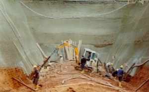
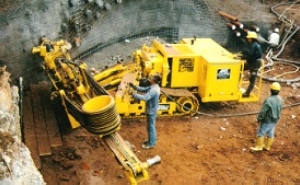
At Oberrieden, the Doorframe Slab Method was utilised for the construction of section B . Construction commenced with the excavation of the loose, fine grained sandy material in a trench excavation down to the crown elevation of the concrete slab. The slopes were cut approximately at a 60° angle and secured by 10 cm thick wwf, reinforced shotcrete layer and grouted pipes. Subsequently, 4.5 m long steel I-beams were rammed into ground at 1 m centers and at an angle of 37° to the vertical to both sides of the future concrete slab. These beams consolodate the ground and create a vault-like brace arch in the ground between them, thereby providing sidewall support for the top heading of the future tunnelling operation beneath the concrete slab.
Following trench excavation and installation of the steel beams, the bottom of the trench is prepared by covering it with a foil to provide a slip layer and the roof shaped concrete slab at a thickness of 0,65 m was cast into the trench . Concreteing of the slab required approximately 305 m³ of concrete and took about 12 hours. After sufficient curing, the trench was backfilled with the previously excavated material which was compacted, covering also the installed instruments for settlement monitoring.
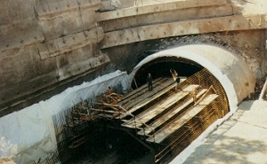
Excavation of the tunnel underneath the roof slab was carried out according to the NATM in a top heading bench and invert sequence using a backhoe with length of advance limited to a maximum of 1 m. Ring closure distance of the complete shell was specifed to 8 m at a maximum. Drivage of the tunnel beneath the slab presented no difficulties. The steel beams supported the side wall in the top heading until lattice girders, wire mesh and the shotcrete were installed.
The concrete slab and the opening underneath were constantly monitored. The slab experienced settlements ranging from 17 mm to 52 mm during backfilling, compacting and tunnel construction. Pressure cells installed in the slab indicated minimal fluctuations during tunnel drivage. The excavation rate amounted to about 3.2 m/day on the average, from the top heading excavation to the required ring closure .
Cut-and-Cover (Length = 23 m)
An approximately 20 m deep trench was excavated to provide for the installation of the starter wall for tunnel drivage beneath the Doorframe Slab on the one side and the Barrel Vault through the railroad embankment on the other. Two rows of 1.20 m diameter bored, concrete reinforced piles were installed at a height of 25 m to secure the trench. In sequence with the excavation, the piles were tied back using anchor beams and pr-stressed anchors . All anchors were pre-stressed with 100 to 520 KN. Each further deepening excavation of the trench was only permitted once the corresponding row of anchors had attained the prescribed working load. These supporting measures were of a temporary nature as the trench was backfilled and the surface restored prior to tunnel construction beneath.
Barrel Vault Method (L = 67 m)
The Barrel Vault Method foresees the installation of a protective vault or load carrying arch above the crown of the future tunnel by means of grouted piles. At Oberrieden, 35 m long steel sleeve pipes were inserted from both sides of the embankment to overlap in the middle in order to construct this vault at the entire length above the tunnel crown. To establish an adequate pre-support, three rows of grouted piles were installed above the tunnel spring line. The maximum cover between the crown of the tunnel and top of the embankemnt was 10 m.
In the first row directly above the tunnel crown, the grouted piles were installed at 600 mm centers. In the second row at approximate distance of 500 mm from the first one, the piles were constructed at 1200 mm centers, and in the third row which was located at a distance of approximately 1000 mm from the second at 1500 mm centers. This third and outermost row primarily served the purpose of ground improvement below the tracks. In total, 162 borings were required, 82 from the west side of the embankment and 80 from the east side.
All borings were carried out using air flushing. An injection container was set up for the grouting operations, which was equipped with accurate pressure and quantity plotters. In total 385 tons of grout material were injected. Following several trials, the water cement ratio for the grout was established at 70:30. Installation of grouted piles was carried out in the following stages:
Stage 1: A 35 m long horizontal cased boring was driven with an external outer diameter of 133 mm using a 75 mm drill bit. Upon completion the drill bit was retrieved.
Stage 2: A steel pipe with an outer diameter of 74 mm and a wall thickness of 3.5 mm was inserted into the casing with externally located grouting and ventilation hoses. The steel pipe was equipped with rubber sleeves at 1 m distances which close 3 openings spaced equally along the pipe perimeter. Subsequently, a bentonite suspension was injected to support the whole when removing the casing.
Stage 3: While withdrawing the borehole casing, weak cement was pumped under slight pressure into the borehole to fill the resulting void, replacing the bentonite suspension.
Stage 4: The borehole opening was closed with mortar after the entire casing was withdrawn. The steel sleeve pipe was now completely embedded in the cement material. After adequate setting of the weak cement, the actual grouting procedure was started.
Using a double packer system, the grout was injected section by section at 20 bar pressures to open up the rubber sleeves and to flow through the surrounding annular cement ring into the ground. Once flowing, a pressure of 2 to 5 bar was sufficient to allow for penetration into the porous embankment material. When the grouting task was completed, the pipe was cleaned by flushing to permit for subsequent injections as necessary. It was estimated that in the first row about 40 liters per 1 m section would be required to accomplish the grouting. During the actual work this amount was much higher resulting in about 100 liter per meter. This already indicated a high void ratio of the embankment material.
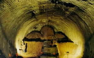
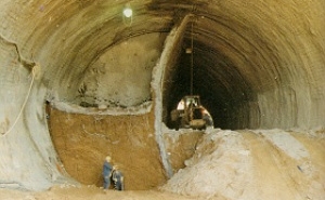
To minimise settlements while excavating beneath the protective Barrel Vault, hip-side-wall excavation was used whereby the cross section was subdivided into four drifts . The first drift comprised excavation of the first half of the crown, and the second drift, excavation of the bench and invert below it. The third drift comprises the second half of the crown, and the fourth drift the bench and invert below it. Support included 35 cm shotcrete reinforced with lattice girders per each excavation round of maximum 1 m and two layers of welded wire fabric for the outer shel. The temporary walls were constructed with 20 cm shotcrete and profile arches. The temporary inverts of the crown drifts were secured with a shotcrete layer of 20 cm. The temproary walls and inverts were removed during drivage of the third and fourth drift. In order to improve the surround soil and provided for abutment supports of temporary and final inverts, 4 m long plastic sleeve grouting pipes were installed .
Using a back hoe, the excavation of the tunnel through the embankment started from the north portal. During excavation it became evident that the installation of the horizontal grouted piles had not been as successful as had been expected. Some drill holes had deviated into the excavation area and the steel sleeve tubes had to be cut during excavation. Others deviated up to 3 m above their intended location, well outside the 300 mm tolerance, creating gaps in the protective vault.
During drivage of the first drift, settlements were small and gradual. However, as the excavation advanced about 30 m, reaching a deposit of dense silty sand and clay which had not taken any grout during barrel vault installation, settlements increased rapidly. These reached magnitudes of 25 mm at track level on top of the embankment. Work stopped immediately and the situation was stablised.
In the meantime excavation of the first crown drift started from the opposite portal. But here again, as soon as this drift approached a location about 15 m distance from the opposite heading, the same sudden settlements occured.
These settlements developed because of the following reasons.
The drilling procedure for the horizontal piles disturbed much loose ground and caused it to shift and settle.
In such blocky ground the grout drained away leaving a void around the steel sleeve tube. These voids collapsed and caused at least half of the settlements of the embankment even before the excavation started.
The water content of the ground had a compacting effect, particularly on the dry sands contained in the embankment fill.
The pockets of silt in the embankment did not take up any grout. This silt is very soft and behaved like a paste thereby causing additional settlements.
Because of the high porosity of the embankment fill it was concluded that further grouting through the steel pipes would not improve the ground since it would nearly fill the embankment from the bottom up .
Voids filled with grout of the highly porous embankment fill.
Instead, the ground was treated using grouting spiles installed radially through the barrel vault. In addition, plastic sleeve grouting pipes were installed ahead of the face. Using these additional support measures, advance progressed at 6 m long intervals alternating excavation/grouting cycles working both portals. During grouting cycles the face was secured with 150-200 mm thick shotcrete layer reinforced with one layer of welded wire fabric.
Excavation and support of the 67 mm long Barrel Vault Section was completed in 85 days working 24 hours/day in two twelve hours shifts seven days a week. This amounts to an average advance rate of roughly 0.8 m/day.
Maximum accumulated settlements resulting from the horizontal drilling and tunnel excavation recorded at 125 mm at one location in the roof of the tunnel and 35 mm at track level.
Jet Grouting
During preliminary design stages of the Barrel Vault Section, jet grouting had been suggested as a method for constructing the grouted piles. After having exposed the ground, it became evident that jet grouting would not have been effective. Even under pressure the grout would have drained into the voids of the embankment leaving vera little grout material above the tunnel crown.In addition, the high pressures associated with jet grouting would have led to a higher compaction of the soft material and thereby to higher settlements of the embankment. Probably the most significant advantage of the method used was the fact that even if not surrounded by grout, steel sleeve tubes provided a significant pre-support of the ground acting in a similar manner as regular rebar spiling installed ahead of the excavation face.
INSTRUMENTATION AND MONITORING
The German Federal Railway Authority imposed high demands on safety since it did not allow for any disruptions to railway traffic. The trains were using the railroad tracks on the embankment without reductions to the 60 miles per hour average speed and the 6 minute frequency interval between trains. Based on these demands, frequent inspections and monitoring using high precision monitoring techniques were employed especially during tunnel construction through the embankment. In addition to conventional geodetic monitoring techniques, a hydraulic based, highly sensitive measuring system was used at the railroad embankment.
Mined Tunnel Section
The interaction between lining and surrounding ground was monitored using convergency and stress measurement cross sections. Deformations of the initial shotcrete lining were monitored for convergency using either 3 or 5 bolts equipped with light emitting diodes at convergency cross sections. In addition, two stress measurement cross sections were established each having 5 concrete pressure cells and 5 ground load cells to monitor stresses within the shotcrete lining and loads imposed by the ground onto the lining. During blasting operations, the nearby 120 year old railroad tunnel was monitored using geophysical measurements (geophones).
Doorframe Slab Section
In addition to convergency and stress measurements as described above, concrete pressure cells installed in the slab and 4 settlement points located directly on the slab were used.
Cut-and-Cover Section
In this section the main concern was to monitor stability and movements of the walls. For this purpose, levelling points along the anchor beams and anchor force sensors were installed.
Barrel Vault Section
Conventional geodetic instrumentation using surface settlement markers at track level and down both sides of the embankment were employed to measure surface deformations. In addition to the direct monitoring of the embankment, instrumentation was also installed at overhead power masts to monitor there inclination due to surface settlements of the embankment. A 70 m long inclinometer was installed passing through the embankment at about 3 m above the tunnel crown to clearly indicate settlement trough as result of tunnel operation.
To comply with high safety regulations, a fully automatic, electronic settlement monitoring system was used to detect movements of the tracks. This system is based on the water levelling principle. Along each side of the track at the outer edges of the embankmenttwo rows of a total of 16 measurement 'beakers' were situated. These were connected to a main tank in the nearby control trailer. All beakers are equipped with an electronic level scanner. Settlements caused a rise in water level compared to the reference tank. The measurement range is 100 mm and can be adjusted as required and the measuring accuracy is 0.1 mm. The electronic reading devices were connected to a central control and processing unit equipped with optical and acoustical displays indicating when limiting values had been reached. The unit transferred all measurement data to a computer in the site management office where the information can be processed at any time into either numerical printout or graphical plots. By means of this system, the movements of the railroad bed were monitored continuously in real time so that potential danger to the train traffic could be detected at once.
SUMMARY AND CONCLUSIONS
The Oberrieden project introduced two innovative tunnelling techniques; the Doorframe Slab and the Barrel Vault Method. In combination with the NATM for subsequent tunnel construction, these methods have proven to be technically feasible regarding the poor ground conditions, especially in the manmade embankment, cost effectiveness, and appealing where alternatives are sought to either minimise or completely eliminate adverse impacts through tunnelling operations on environment and surface activities.
In the case of the Doorframe Slab Method, expensive bulk operations typically associated with cut-and-cover constructions could be reduced to a great extent. The actual tunnelling was carried out under a completely restored surface. The Barrel Vault Method enabled high speed rail traffic to frequently cross the railroad tracks without any disruptions for the entire construction period except for one instance when traffic was hindered for a 12 hour period. The complete project is estimated to be about between 30 and 80 percent less expensive compared to estimates for a rail viaduct and road tunnel in jacked option.
Considering tunnel construction, especially in urban areas where requirements to minimise impacts on the environment are becoming more and more restrictive, these tunnelling techniques represent attractive options. For example, the Doorframe Slab Method has been recently foreseen in the preliminary design for a road tunnel beneath an existing airport runway in Dallas, Texas.
ACKNOWLEDGEMENTS
CLIENT: Hessisches Strassenbauamt Eschwege on behalf of the Federal Ministry of Transport
GEOLOGY: Hessisches Landesamt für Bodenforschung, Wiesbaden.
STRUCTURAL REVIEWERS: Prof. Duddeck and Partner Brunswick; and for the German Federal Railway Authority Dipl.-Ing. W. Romberg, Darmstadt, Dipl.-Ing. L. Cezanne, Frankfurt/Main.
CONTRACTOR: Alfred Kunz GmbH & Co., Munich.
REFERENCES
- Desenritter, S. And Zeidler, K., 1992, "The Schürzeburg Tunnel, Oberrieden," Tunnel, Feb., pp.58-64.
- Deinhard, M., Prinz, H. And Zeidler, K., 1991, "Oberrieden Road Tunnel: Variations on an NATM Theme," Tunnels and Tunnelling, Nov., pp. 49-51.
- Sauer, G., 1988, "When an Invention is Something New: from Practice to Theory in Tunnelling," Transactions of the Institution of Mining and Metallurgy, Section A, Mining Industry, Vol. 97, Apr., pp. A94-A108.
- Sauer, G., 1992, "The Schürzebergtunnel, Oberrieden," Sept., Proceedings, First International Symposium on Tunnel Construction and Underground Structures, Ljubljana, Slovenia, Chap.2, pp. 151-165.
