You are here
Featured Projects - Silver Line
Project Overview
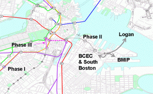
The Silver Line will become a complete transit line of the Massachusetts Bay Transportation Authority (MBTA) in Boston, MA with the design and construction of Silver Line Phase III that will link two transit improvement projects:
Phase I - the Washington Street Replacement Service Project a dedicated busway lane with seven stops along a 3.2 km (2 mile) widened section of Washington Street from Dudley Station in the south to the New England Medical Center Station (NEMC)
Phase II: the South Boston Piers Transitway Project this alignment is progressing towards operating services from Boston?s South Station, under the historic Russia Wharf building, across Fort Point Channel in immersed tube, and through cut-and-cover stations at Courthouse and World Trade Center before surfacing at D Street to continue along South Boston?s waterfront and on through the Ted Williams immersed tube tunnel to Logan Airport.
Services by the Massachusetts Bay Transportation Authority (MBTA) already operate on Phase I since July 2002 while Phase II is under construction and should open in Spring 2004. The two sections will operate independently of each other with the buses turning at the end of each line section. In addition new stations will be designed at Chinatown Station (Orange Line) and Boylston Station (Green Line) providing access from the Silver Line to these existing MBTA Subway Routes
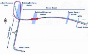
Phase III: link between Phase I and II the alignment start at NEMC towards Tremont street, (see Figure 2) with a new Station underneath existing Boylston Station, a loop underneath the Boston Common into Essex Street with a new Station underneath the existing Chinatown Station, processing in Essex Street underneath the existing Central Artery Tunnels at Dewey Square and connects the new alignment at South Station
Alignment Sections:
Tunnels for the Phase III central section lie up to 27 m (81 ft) below the surface and in primarily soft sedimentary soils, Boston Blue Clay and till. Excavation technique is currently based on NATM station caverns, complex underground junctions (escalators, connection tunnels etc.) and with either NATM shotcrete-lined or EPB TBM running tunnel tubes lined with precast concrete segments.
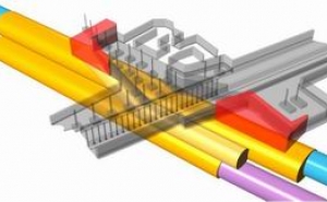
For the most part, the central route runs beneath public right-of-ways. To avoid the delay to acquire approval to pass beneath private property, stations are located directly beneath existing MBTA stations. The stacked running tunnel configuration with a stacked station configuration at Chinatown is adopted to keep the work directly beneath Essex Street.
Based on the existing geotechnical information tunneling will be in soft ground.
The ground water level is about 10 to 20 feet below the ground surface. The control of groundwater will depend on the tunneling method selected. In general tunneling may be carried out using NATM or tunnel boring machines which may include open or closed faced types. Ground improvement measures which may include forms of grouting may be applied in connection with dewatering measures to control the amount of dewatering needed and to control dewatering associated settlements.
The most interesting tunnel segments/sections and construction techniques for the entire base case alignment can be described as follows:
1. South Station / Cut & Cover Box
2. Essex Street Running Tunnels / NATM or EPB TBM Excavation Specialties in this Section are:
- Underpass of the Central artery/Dewey Square Tunnel (NATM - Barrel Vault Method)
- the tunnels are starting side by side and twisted to stacked Tunnel configuration after the underpass of the existing Central Artery Tunnel
3. Chinatown Station / NATM Excavation
- two stacked Station Tunnels underneath the existing Chinatown
- Station - connection to the existing Stations
4. Boylston Station / NATM Excavation
- new station is located underneath the existing Green Line Station
5. Loop in Boston Common / NATM Excavation
6. Tremont Street Double Track Tunnel / Mined Tunnels using NATM principles
7. Portal at New England Medical Hospital
Single running Tunnel:
Cross Section: approx. 454 ft² / 43 m²
Total Tunnel Length: approx. 6632 ft / 2020 m
Station Tunnels:
Cross section: approx. 810 ft² / 75 m²
Total Tunnel Length: approx. 1000 ft / 305 m
Double Track Tunnels:
Cross section: approx. 750 ft² / 70 m²
Total Tunnel Length: approx.1375 ft / 420 m
NATM Excavation Techniques
The NATM Excavation approach with shotcrete for immediate support in combination with pre-support and ground improvement techniques has demonstrated that costly underpinning schemes may generally be avoided. Ground improvement techniques range from simple injection of grouts into the soils to more elaborate methods including jet grouting and ground freezing. These ground improvement methods may be installed either prior to tunneling from the surface or from within basements of buildings underneath which tunneling will occur or as part of the tunneling operation from within the tunnels. In contrast to machine driven tunneling where late installation of support behind the shield (ribs and lagging, steel-, or segmental linings, etc.) may cause notable settlement, settlements associated with shotcrete supported tunneling can be controlled by the early installation of shotcrete directly behind the excavation face. This support is (smooth( and provides direct contact with the ground thereby avoiding cavities or gaps between lining and ground which are often another contributing factor to tunneling induces settlements. This ability to control settlements reduces the need for underpinning.
Instrumentation and Monitoring
Because of the close proximity of the mined tunnels to existing surface and subsurface structures as well as utilities a thorough instrumentation and monitoring system will be required. Instruments will be installed to observe the tunneling performance and the behavior of the nearby structures as they may be affected by the tunneling operation. All structures (e.g. existing Chinatown Station) and utilities that are expected to lie within a general influence zone of the proposed tunneling operation will be appraised by preconstruction documentation and an instrumentation baseline will be established prior to start of any operation. Upon start of the tunneling operation a regular monitoring program will be in place which will be intensified when the active tunnel face is within an immediate influence zone.
Tunnel Waterproofing
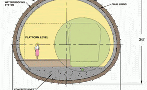
The NATM Sections of entire alignment will utilize a double lining system an outer primary lining for temporary ground support and an inner final lining for permanent, long-term support. The inner lining typically consists of a cast-in-place lining but a alternative design of a shotcrete final lining is also feasible.
Waterproofing systems using flexible membranes have proven to achieve dry underground structures on many urban tunneling projects. The membrane will be placed between the initial and final lining applying a closed system.The closed system wraps the entire tunnel into the waterproofing membrane creating a (submarine( like structure. With this system the groundwater level returns to pre-construction conditions and no long-term drainage is associated with this system.
The Actual Situation
For the MBTA the Dr. Sauer Group is acting as sub consultant to the lead consultant URS/DMJM+Harris with the focus on the various tunnel excavation options especially at the Mined Tunnel Sections of the project to develop and evaluate the best solution from the technical but also from economical point of view. Several new resp. additional alternatives were developed and are now under review. These additional alternatives are concentrated on
- new and additional station platforms
- reducing the impact to historical areas (e.g. Boston Common)
- constructability of underground structures
- rider ship performance
- access to existing station structures
- future extensions etc.


