You are here
Heathrow Express Rail Link NATM Trial Tunnel
June 1, 1992
London, UK


World Tunneling Magazine, June 1992
A site trial to establish the feasibility of using NATM in London Clay for the high speed rail link stations below the airport terminal building.
INTRODUCTION
The Heathrow Express Link will provide a 15 minute high speed rail service between Paddington Station in central London and Heathrow Airport. The first 18 km of the total 25 km route will run on the existing Paddington - Reading railway corridor. A new 7.25 km spur running for the most part in tunnel will provide the airport with underground stations at the Central Terminal area (Terminals 1, 2 & 3) and Terminal 4. Provision will also be made for a link to the proposed Terminal 5. The 5,5 km long tunnelled section will pass under the M4 motorway with the portal located to the north.
CONSTRUCTION CONSIDERATIONS
Tunnelling will be in London Clay, a homogeneous, impermeable an competent material which has proved to be highly suitable for underground excavation. It is the suitability of London Clay as a tunnelling medium which allowed early and extensive development of Central London`s underground space.
At Heathrow, the 8 km of 5.675 m internal diameter running tunnels (a 3 km thin tube length from the portal to the Central Terminal Station and a 2 km single track link to Terminal 4) are expected to be excavated using traditional open faced tunnelling shields or non-pressurised TBMs with rings of expanded precast concrete segments providing the initial support and permanent lining.
The stations and step plate junctions are to be excavated largely using the NATM. This tunnelling method has resulted in substantial time and cost savings when compared with traditional segmentally lined, shield or hand excavated station works. The basic difference between traditional methods and the NATM is the use of shotcrete instead of precast concrete or cast iron segments as the initial ground support.
This basic difference encompasses several advantages. These include:
- Flexibility to accommodate any shape of underground opening or junction
- Shorter cycle times
- Flexibility to set cycle advance lengths and the excavation sequence to suit the prevailing ground conditions
- More cost effective use of materials
- Less labour intensive
- Rapid mobilisation using standard excavation equipment
- Lower capital investment for essential equipment
- Elimination of shield assembly and dismantling chambers
- Easier installation of a high quality waterproofing system
PROJECT DEVELOPMENT
BAA, the private enterprise owner of Heathrow Airport, opened discussions with British Rail concerning rail services to the airport in 1987. In July 1988 the Government approved in principle a joint proposal to build a new rail link from Paddington. Feasibility studies culminated in Royal Assent of the projects private parliamentary bill in the summer of 1990.
In 1989, Consulting Engineers and Construction Management Contractors were engaged. Realising the potential savings of NATM, Dr Gerhard Sauer, a recognised design specialist was invited by the Management Contractors Taylor Woodrow Management Ltd, to explain to BAA and all parties concerned the applicability of NATM for the underground station of Heathrow.
This generated considerable interest and the Dr Sauer company was retained to undertake a feasibility study and cost estimate for the NATM design and excavation of the stations. This indicated substantial time and cost savings over traditional methods. These findings were substantiated by six well experienced Continental NATM contractors who were invited to respond to a questionnaire from BAA. On the strength of this, BAA chose the NATM to the exclusion of all other tunnelling methods for the Heathrow stations. The UK office of the Dr G Sauer Company was engaged as specialist NATM designer.
TRIAL TUNNEL
One area of specific concern remained.. Would the NATM prove as successful in London Clay as it has proved in other soft ground?
While the NATM had been previously used in the UK - most notably for the access drifts to British Gypsum`s new potash mine at Barrow-upon-Soar in 1986, for various sections of the Channel Tunnel in 1988 and for the A20 highway tunnel through Roundhill in 1991 - this would be the first application of the NATM in London Clay. Although London Clay is considered by Continental experts as being among the more competent types of soft ground in which NATM has been used, there was concern about its practical suitability in this type of clay.
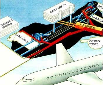
The greatest concern was the ability of the NATM to control and limit settlement. This is particularly important given the location of the stations directly beneath existing terminal buildings and close to other sensitive airport facilities (see Illustration). The overburden between the station and the surface is typically about 22 m.
To allay these concerns, the project team proposes the execution of a trial tunnel with intention of satisfying the following objectives:
- To demonstrate that NATM excavation of the stations can be undertaken without causing ground movements that could lead to structural damage to ground level buildings and other underground installations;
- To enable tenderers for the NATM station works to inspect exposed London Clay;
- Excavation of the first sidewall drift of the Type 2 sequence.
- To provide information to designers and tenderers about the properties and behaviour of London Clay when excavated;
- To observe ground movements above and around the trial tunnel;
- To us data gathered to predict ground movement in the main station areas;
- To establish work procedures that reduce ground movements for application in critical areas of the main station works.
This proposal was adopted and in January 1992, the Kier/Lilley/Kunz joint venture won the trial tunnel contract with a tender price of about £1.2 million. Work on site started in February 1992 and was completed by June 1992.
With limited NATM experience in the UK, the trial tunnel was designed to provide a practical introduction of the technique, confirm its applicability in London Clay and allow refinement of the final NATM station design. "It will provide information on settlement which will indicate where pre-emptive measures can be taken and will generate more confident tendering with less risk premium or contingencies included in each tender", said Paul Fox, Project Manager for BAA.
TRIAL TUNNEL OBSERVATION
The performance of the NATM in its ability to control settlement and residual ground movement is monitored by a series of in-situ measuring devices which are logged at frequent and regular intervals. Interpretation of the collected data warns of potential danger and provides information upon which modification of the excavation can be made.
The Transport Research Laboratory (TRL) was engaged to install, read and collect data from the surface instrumentation. Instrumentation in the tunnel was installed by engineers from the Dr Sauer Company and Lead Consultant Mott MacDonald.
The surface instrumentation comprise:
- Precise levelling points
- Geodetic points
- Inclinometers
- Magnetic ring extensometers
- Each measuring station within the tunnel incorporated:
- Convergence points
- Earth pressure cells
- Shotcrete stress cells
- Dowel load cells
TRIAL TUNNEL DESIGN
The NATM trial investigated the performance of three different excavation and support sequences.
TYPE 1
- Twin sidewall drift face excavation
- Advance per cycle limited to 1 m
- Lattice girder on 1 m centres
- 25 mm diameter * 3 m long driven dowels as required by ground conditions
- Twin side wall drifts excavated a minimum 25 m in advance of the central core excavation
- Maximum 5 m distance between top heading of sidewall drift and sidewall invert
- Maximum 7 m distance between top heading of central core and invert
TYPE 2
- Single sidewall drift face excavation
- Advance per cycle limited to 1 m
- Lattice girder on 1 m centres
- 25 mm diameter * 3 m long driven dowels as required by ground conditions
- Left sidewall drift excavated a minimum 25 m in advance of right sidewall drift
- Maximum 5 m distance between top heading of sidewall drift and sidewall invert
TYPE 3
- Crown, bench and invert face excavation
- Advance per cycle limited to 1 m
- Lattice girder on 1 m centres
- 25 mm diameter * 3 m long driven dowels as required by ground conditions
- Maximum 5 m distance between top heading and bench
- Top heading and bench excavated a minimum 25 m in advance of invert
TRIAL TUNNEL CONTRACT
The trial tunnel contact comprised a 10.65 m internal diameter * 25 m deep access shaft and 100 m of 8 m diameter "station tunnel". For expediency, the shaft was sunk using conventional caisson and underpinning methods and is lined with bolted precast concrete segments.
Excavation of the trial tunnel started with TYPE 1. A double side drift sequence designed to provide the greatest degree of control over ground movement and settlement. This was followed by Type 2 a general purpose single side drift sequence. The trial was completed by a heading and bench sequence with a modified invert profile, which was devised to reduce settlement by providing additional temporary restraint before full ring closure was achieved. Each trial section was progressed for at least 30 m providing an adequate length over which meaningful data could be accumulated.
The Kier/Lilley/Kunz joint venture used a Liebherr 902 excavator for tunnel advance. Once transported to the shaft, muck was lifted to the surface in a 3 m³ skip. "The aggregates for the dry shotcrete mix are bought in from a local supplier", explained Eric Snowdon, Project Manager for the joint venture "and we are applying it using a Meynadier shotcreting unit with a 8 m³/hour capacity" Lattice girders were supplied by Caledonian Mining Ltd.
Work is progressed 24h/day, 7 days a week. This was considered necessary since the ability of the NATM concept to control excessive ground movement depends largely on a continuous working cycle which avoids long delays between the various operations. The tunnelling crew for each shift numbered about six with Kunz of Germany providing the experienced NATM miners. Supervision was carried out by Taylor Woodrow Management with design support on site from Mott MacDonald and the Dr Sauer Company.
TRIAL TUNNEL FINDINGS
Finite element methods were used during design for predictive deformation, pressure and settlement modelling. These were compared to actual settlement measurements following the trial and found to be in reasonably close agreement. Similarly, earth pressure and average shotcrete pressure showed reasonable correlation between calculated and measured values. Concrete stress levels were also shown to remain within designed limits throughout and following the trial.
Overall settlement related to progress of each type of excavation shows a clear relationship between total settlement and ring closure with partial ring closures during the sequential excavation methods being monitored by temporary interruptions in the settlement trends. Unexpectedly the Type 2 sequence proved to have the better settlement performance over type 1. This was possibly for two reasons:
- The type 1 sequence suffered more from learning curve period at the start of the trial.
- The time required for total ring closure was less for Type 2 than for Type 1.
The Type 3 sequence was more disappointing as it had been hoped that the modified temporary invert profile would replicate ring closure inhibiting settlement. In the event this was not the case, probably due again to learning curve factors and insufficient bearing capacity characteristics of the ground for the method to work adequately. Consequently a larger settlement was recorded for this Type and even though the total rime to full ring closure was similar to Type 2, no partial Overall settlement related to progress of each type of excavation shows a clear relationship between total settlement and ring closure with partial ring closures during the sequential excavation methods being monitored by temporary interruptions in the settlement trends. Unexpectedly the Type 2 sequence proved to have the better settlement performance over type 1. This was possibly for two reasons:
- The type 1 sequence suffered more from learning curve period at the start of the trial.
- The time required for total ring closure was less for Type 2 than for Type 1.
The Type 3 sequence was more disappointing as it had been hoped that the modified temporary invert profile would replicate ring closure inhibiting settlement. In the event this was not the case, probably due again to learning curve factors and insufficient bearing capacity characteristics of the ground for the method to work adequately. Consequently a larger settlement was recorded for this Type and even though the total rime to full ring closure was similar to Type 2, no partial ring closures were achievable by this method.
Nevertheless, all these methods clearly demonstrate the suitability of the NATM in London clay and the NATM Trial resulted in the following findings:
- Confirmation of the practical and economic advantages of NATM
- Confirmation of the suitability of NATM in London Clay
- Surface settlement from NATM was equal to or less than could have been expected from the highest standard of shield driven segmentally lined tunnelling
- Surface settlement expressed as a percentage of face area of less than 1.5% can be achieved in a "Green Field Site"
- Low surface settlement is achievable without resort to adoption of special measures
- Limitation of ground movement and surface settlement is directly related to the time taken to close the NATM ring
PROGRESS TO DATE
The £60M contract for the main tunnelling works for the running runnels, Central Terminal Area and Terminal 4 stations was let in February 1994. The running tunnels are to be largely shield driven and segmentally lined whilst the station complexes, running tunnel junctions and crossovers will be undertaken largely using the NATM and based on designs and layouts prepared by the Dr. Sauer Company Ltd. in association with Mott MacDonald.
Completion of the tunnelling works was in the Spring of 1996 with the rail link became operational at the end of the following year.
CLIENT: Heathrow Airport Limited
LEAD CONSULTANT: Mott MacDonald Group
CONSTRUCTION MANAGER: Taylor Woodrow Management Ltd.
SPECIALIST TUNNELLING ADVISOR: Maurice Gooderham
SPECIALIST NATM ENGINEER: Dr G Sauer Company Ltd
TRIAL TUNNEL WORKS CONTRACTOR: Kier/Lilley/Kunz joint venture
SETTLEMENT MONITORING: Transport Research Laboratory (TRL)