You are here
Tunneling Under Dulles Airport
June 1, 2003
Herndon, VA, USA
Rapid Excavation and Tunneling Conference - Proceedings 2003
ABSTRACT
The Metropolitan Washington Airports Authority (Authority) has undertaken a tremendous expansion of Washington Dulles International Airport in Fairfax, Virginia, including upgrading passenger transportation between concourses. The first stage of this expansion envisioned a shallow cut-and-cover pedestrian tunnel between the Main Terminal and Concourse B with associated vertical circulation structures. At the beginning of the design contract, the Authority’s consulting team of Earth Tech, formerly Kaiser Engineers, and the Dr. G. Sauer Corporation compared the cost and disruption of constructing the tunnel as a cut-and-cover structure to mining the tunnel using the New Austrian Tunneling Method (NATM). Upon review, the Authority endorsed the latter method.
GENERAL DESCRIPTION OF THE PROJECT
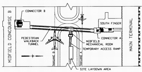
The pedestrian tunnel referred to as the Pedestrian Walkback Tunnel is a 235-m-long (770-foot-long) underground pedestrian structure or corridor running north-south and connecting Washington Dulles International Airport’s Main Terminal to Midfield Concourse B (see Figure 1). The South Finger, a part of the Main Terminal that extends south of the main building and houses the Airport Traffic Control Tower and mobile lounge docks, lines up with the annex on the north side of the Concourse B which also houses mobile lounge docks. The tunnel was positioned to the east of the South Finger and to the south of the Main Terminal in order to allow maximum flexibility in planning the future passenger transportation system.
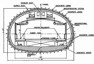
The Pedestrian Walkback Tunnel was designed to house a fixed pedestrian corridor flanked with two moving walkways (see Figure 2). At the north end of the tunnel a 30 m long by 15 m wide by 15 m deep (100 ft x 50 ft x 50 ft) cut and cover structure, Connector A, brings passengers from the tunnel level to the Main Terminal baggage claim at the apron level and to the Main Terminal concourse level via a temporary bridge which is also a part of this contract, using elevators, escalators and stairs. At the south end of the tunnel a 55 m long by 32 m wide by 17 m deep (180 ft x 105 ft x 55 ft) cut and cover structure, Connector B, brings passengers from the tunnel level to the Concourse B level via similar vertical circulation elements. Both connector structures partially extend two stories above grade. In the future the Pedestrian Walkback Tunnel can be extended through the south end of Connector B, under Concourse B and continue south to other future concourses, therefore, knockout panels had to be anticipated in the design.
Due to funding constraints the original project was divided into two parts; the Shell Package, which includes construction of the Connector A, and the tunnel and the Finish Package, which includes construction of the Connector B and installation of all of the mechanical, electrical and architectural finishes in both connector structures as well as the tunnel. The Shell Package was completed in 2001 and construction of the Finish Package started in the fall of 2002 and is projected to be completed in the summer of 2004.
CUT AND COVER VS. NATM
The Authority originally envisioned the Pedestrian Walkback Tunnel being constructed using standard cut and cover construction techniques. During the design process it was decided to investigate mining the tunnel using the New Austrian Tunneling Method (NATM) also known as the Sequential Excavation Method (SEM). As the tunnel passes under two taxilanes, cut-and-cover construction had the obvious disadvantage of disrupting airport operations and requiring the taxilanes to be closed down for an extended period of time; thereby reducing the access to the gates on the north face of Concourse B. A list of pros and cons for both options was prepared as well as cost estimates and construction schedules. The construction duration was similar for both construction options; however, the mined option offered an overall savings of about 3.3 million dollars or 14% of the construction cost. With the apparent cost savings coupled with much less disruption, the Authority modified the design scope to a mined tunnel.
TUNNEL GEOMETRY AND ELEVATION
The Pedestrian Walkback Tunnel was envisioned to house two moving walkways each 1 m (3.3 ft) wide with a 5.8 m (19 ft) wide stationary walkway between them. Leaving additional space for the moving walkway equipment, the horizontal space needed was 9.8 m (32 ft) with a minimum height of 2.7 m (9 ft) (see Figure 2). The curved or ovoid tunnel shape, developed around a clearance envelope which included the walkway space as well as ventilation, utilities and architectural finishes, keeps the ground and the lining in compression and avoids stress concentrations.
Originally the Pedestrian Walkback Tunnel was designed with 5.5 m (18 ft) of cover. As a cost reduction, the Authority asked the designers to investigate raising the tunnel to reduce the required vertical circulation and to match the elevation of the future people mover structures. Preliminary frame analysis calculations were performed modeling the worst loading conditions, under one of the taxilanes with a 747-400 with a weight of 567,000 kg (1.25 million pounds), and at the connector structure to evaluate the effect on the existing South Finger. The result showed that the tunnel could be raised to where it had 4.6 m (15 ft) of cover.
SITE LAYOUT AND CONSTRUCTION SEQUENCE
Since the tunnel was designed with cut-and-cover structures at both ends, the obvious construction sequence would be to entirely excavate one of the connectors then mine the tunnel and transport the tunnel muck through the connector structure. However, due to the lack of surface construction space at the connectors, the site laydown area was placed in a grass strip between the taxilanes. This area was large enough to accommodate a limited amount of construction and storage trailers, temporary muck storage, (muck hauling from the airport was restricted to between 11:30 pm and 5:00 am) and a batch plant with storage for materials and a sediment basin. In order to eliminate construction debris, or foreign object debris (FOD), from accumulating on the taxilanes, the area was depressed about 2.4 m (8 ft) lower than the surrounding ground and a height restriction was set so that the line of site from the control tower to the taxilanes was not obstructed. A ramp from the site laydown area extending towards the tunnel was provided as access to the tunnel, thereby making the tunnel construction an independent construction activity from the cut-and-cover structures. This had an added positive benefit of reducing the length of the construction schedule. At the end of the ramp a portal and a short length of tunnel, known during construction as the Temporary Access Tunnel, was designed and constructed prior to turning north and south in the Pedestrian Walkback Tunnel. The Temporary Access Tunnel would be converted into a midfield mechanical room with a vent shaft and the ramp and site laydown area would be backfilled and restored to the original condition.
GEOLOGY
The field exploration and testing was performed under the direction of Thomas L. Brown Associates, PC of Washington, D.C. In addition to drilling a series of test borings up to 3.1 m (10 ft) below the tunnel invert and 1.5 m (5 ft) below the cut-and-cover structures, a seismic refraction survey was conducted in order to determine the bedrock depth and the rippability of the bedrock. In order to monitor the groundwater, monitoring wells were installed in two borings. The field and laboratory tests were performed and the results were submitted in a geotechnical report dated July 14, 1999. The report outlines the subsurface conditions to consist of the following:
- Concrete or asphalt pavement underlain by a gravel bed.
- Disturbed soils and/or fills consisting generally of stiff to soft clay to silty fine to coarse sand with little rock fragments.
- Residual soil consisting of reddish brown clays with some sand to silty sand.
- Decomposed, weathered and highly jointed siltstone with Rock Quality Designation (RQD) values between 0 to 30%.
- Bedrock consisting of moderately jointed siltstone with a trace of calcite and clay veins throughout. RQD values between 36 to 99%.
- Groundwater level located approximately 2.4 m (8 ft) below the surface.
In order to minimize impact on airport operations and due to the geology, all of the excavation was expected to be done with road headers and rippers. Due to the seismic refraction survey as well as the testing results, competent rock was detected, therefore provisions were added to the contract documents to allow controlled or smooth blasting as a means to pre-split or loosen the rock which would then be excavated with a road header.
EXCAVATION AND SUPPORT
Pedestrian Walkback Tunnel
The tunnel excavation and support is primarily dependent on the geologic conditions and well as the shape of the structure. As the top heading was predicted to be located in residual soil or decomposed rock, settlements were limited by using presupport, i.e., rebar spiling, for the entire length of the tunnel. In soil conditions the rebar spiling is simply pushed into the ground ahead of the excavation face. In rock conditions holes are drilled, filled with grout then the rebar spiling is installed.
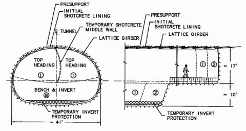
Another measure to reduce settlements was to divide the tunnel into two top headings or half face drifts as shown in Figure 3. The half face drift is supported by half of the initial shotcrete lining in the crown and a temporary shotcrete middle wall. One half face drift would advance ahead of the other by no more than 5 rounds and no less than one round. The design envisioned that the top heading half face drifts would advance in alternating faces toward a connector structure in about the same time it would take to excavate the connector structure, therefore as there was only one access for the mucking operation through the Temporary Access Tunnel, the bench/invert would be excavated after the top heading was completed.
The design included two excavation and support classes and a tool box of additional support measures which were employed as necessary. Both excavation and support classes consisted of pre-support; one was installed on 30 cm (12 in) centers every round and the other was installed on 20 to 30 cm (8 to 12 in) centers every other round. After the pre-support was installed, one half face top heading drift was excavated in either 1 m (3'-4") or 1.5 m (5'-2") rounds depending on the excavation and support class and immediately supported with 5 cm (2 in) of fiber reinforced shotcrete. The remaining 15 cm (6 in) of fiber reinforced shotcrete would be installed after the lattice girder was erected. After the top heading holed through a connector structure then the bench/invert would be excavated in either 2 m (6'-8") or 3.1 m (10'-4") rounds and supported with lattice girders and fiber reinforced shotcrete. During construction the Contractor proposed an alternative bench excavation which consisted of first removing the plug, a trapezoidal shaped area from the middle of the bench, followed by removing and supporting the wings which were the remainder of the bench. Additional measures were detailed in the design to be used as required by ground conditions included additional rebar spiling, grouted pipe spiling and metal sheeting.
Connector A
An initial geological mapping was performed by the contractor using a 12.2 m (40 ft) deep observation shaft in Connector A which identified several important shear zones across the cut faces with highly erratic joint patterns and groundwater located 2.4 to 3.6 m (8 to 12 ft) below the ground surface with the possibility of perched water conditions. This corroborated the geotechnical report which described highly weathered and highly jointed rock and a groundwater level 2.4 m (8 ft) below the surface. Excavation for Connector A was performed in open cut through residual soil and decomposed rock. Sound rock appeared at the bottom of the excavation. In the upper zone of the residual soil, the contractor selected soil nailing method for the excavation support system. In the decomposed rock, the contractor selected # 8 rock anchors spaced distances varying from 1.8 to 3 m (6 to 10 ft) depending on the rock condition. Excavation was performed using controlled or smooth blasting methods resulting in negligible impact on the adjacent Main Terminal building. The soil nailing and rock anchors were covered with a layer of shotcrete reinforced with two layers of wire mesh.
Connector B
Excavation will begin in spring of 2003. This excavation demands special consideration as the existing Midfield Concourse B building is flanking the southern portion of the excavation. The approach for the excavation of Connector B requires the contractor to be solely responsible for the design and installation of the excavation and support system and for the integrity of the surrounding structures. Similar to the Connector A, the excavation support system will include tiebacks with a 1.5 factor of safety and shotcrete as temporary support during construction.
The existing Midfield Concourse’s foundation consists of 1.2 m (4 ft) diameter caissons which will be exposed during construction of Connector B. In fact, the connector structure will extend below the anticipated bottom of the caissons therefore underpinning will be required. Five different underpinning options were evaluated for risk and cost. Based on the results, the designer recommends installation of an augered concrete filled secant pile wall system to reinforce the rock pillar below the caisson tips. The secant pile wall system should include tie-backs for lateral support as the connector excavation progresses and should extend a minimum of one diameter below the bottom of the excavation.
MONITORING
Prior to construction of Connector A and the Pedestrian Walkback Tunnel a matrix of surface and shallow subsurface monitoring instruments were installed in the taxilanes and during construction tunnel monitoring points were installed in the initial tunnel lining. The surface monitoring points consist of a set of four nails which were fired into depressions in the concrete slab. Shallow subsurface monitoring points consist of a nail fired into a depression in the concrete slab adjacent to a curb box in which a rebar was driven into the ground.
For each shallow subsurface monitoring point two readings would be taken; one on the nail and one on the rebar. The readings could be compared in order to assess the amount of voids that may occur under the slab which was being bridged by the slab. Other subsurface instruments similar to the shallow subsurface monitoring points are the utility monitoring points which were used to monitor a ductbank which contained fiber optic communications cables which could not be disrupted. During construction of the tunnel convergence bolts were installed in the shotcrete lining in order to monitor tunnel lining movements so that additional support measures could be installed as required.
Before excavation can start at Connector B, surface monitoring points, utility monitoring points and inclinometers will be installed outside of the excavation area and initialized. Due to its proximity to the excavation, the underpinning of the existing caissons and its glass composition, the Concourse B columns and beams will be monitored using tiltmeters that will be installed and initialized prior to excavation. During excavation bolts equipped with survey targets will be installed at the support of excavation in order to observe possible movements and allow for additional support measures as required.
WATERPROOFING SYSTEM
Once a smoothing layer of shotcrete was applied to the initial tunnel shotcrete lining and the tie-back and shotcrete support of excavation of the connector structures, a layer of geotextile was installed with PVC disks and nails (see Figure 4). Then a layer of flexible PVC membrane was welded to the disks. The designer chose to use PVC waterproofing because of its flexibility and ability to stretch if the structures shift or settle after construction. At the airport there is a potential for hydrocarbons to be present in the groundwater however, it was determined that the only the plasticizers which make the PVC flexible are affected by jet fuel. Therefore, in an independent study by MWAA it was determined that PVC would be the waterproofing material of choice for future projects.
FINISHED STRUCTURES
After the waterproofing system was installed a cast-in-place concrete invert and final concrete lining were anticipated. The concrete invert was sloped toward the center of the tunnel to a drainage slot (see Figure 2). As the tunnel structure was totally level the drainage slot was sloped in the invert to one of three drainage sumps. The thought was that in the event of a sprinkler discharge water would eventually collect in the drainage sumps that would be pumped to the Mechanical Room sump. This sump would also collect the drainage from the elevator pits in Connectors A and B which would be pumped to an oil/water separator before discharging to an existing storm sewer. The contractor proposed and submitted calculations to reinforce the cast-in-place concrete invert with steel fibers in lieu of the rebars specified in the design; this change was approved. Concrete curbs or short walls structurally tied to the concrete invert were designed to support the stationary and moving walkways as well as the architectural walls.
Due to the relatively short length of the tunnel, 235 m (770 ft) and the large size of the cross section as well as the fact that the final lining would be hidden from public view by the architectural finishes, the Contractor proposed, and was given the approval, to install a reinforced shotcrete final lining instead of a cast-in-place lining. Unistruts that were embedded in the shotcrete lining provide the means for hanging the mechanical ventilation, the waterlines for the sprinklers, the electrical, communications and security conduits as well as the architectural ceiling panels and lighting (see Figure 5).
Access Tunnel was finished with a shotcrete final lining and with the addition of a raised floor platform and partitions it will be transformed into a midfield Mechanical Room. This room will house a sump to which the three tunnel sumps are pumped as well as elevator sumps from both Connectors A and B, exhaust fan and ventilation shaft for smoke evacuation and a janitor’s closet.
Since the tunnel and Mechanical Room are located within the Airport Operation Area (AOA) where security is critical, no exiting to the surface was provided. In the event of an emergency the tunnel is separated into two segments by means of fire-rated accordion-like folding partitions which are concealed in pockets at each end of the tunnel as well as at the Mechanical Room. The partitions will be equipped with panic devices which allow emergency egress from either compartment.
The Connector A foundation consisted of caissons taken to rock, which minimized the impact on the South Finger basement walls and accommodated the future people mover system, and a four foot thick mat footing which also adds weight to the structure to compensate for the buoyancy effects of the groundwater. The walls were designed for groundwater and earth pressure, mobile lounge loads, airplane loads consisting of a DC-9 with a weight of 54,430 kg (120,000 pounds) and vary in thickness with a maximum thickness of 1.2 m (4 ft).
The Connector B cut-and-cover box was designed based on the assumption that the west wall will be excavated in the future to accommodate a people mover station. This condition will create an unbalanced loading condition which required a second reinforced concrete wall that will be removed at such time. The walls were designed for soil and hydrostatic pressure as well as mobile lounge loads and airplane loads consisting of a 747-400 with a weight of 567,000 kg (1.25 million pounds) and the walls vary in thickness depending on their depth with a maximum thickness of 1.4 m (4'-6"). As the entire structure is enveloped with a waterproofing system the foundation consists of a five foot thick mat footing which also adds weight to the structure to compensate for the buoyancy effects of the groundwater.
BIBLIOGRAPHY
- Brown, T.L. and S. Ndeti, “Pedestrian Walkback Tunnel Package Geotechnical Report”, August 1998, prepared for Metropolitan Washington Airports Authority.
- Brown, T.L. and S. Ndeti, “Pedestrian Walkback Tunnel Shell Package Geotechnical Report”, August 1999, prepared for Metropolitan Washington Airports Authority.
- Kaiser Engineers, Dr. G. Sauer Corporation, et al, “Pedestrian Walkback Tunnel Package Design Report”, March 1999, prepared for Metropolitan Washington Airports Authority.
- Kaiser Engineers, Dr. G. Sauer Corporation, et al, “Pedestrian Walkback Tunnel Finish Package Design Report”, August 2001, prepared for Metropolitan Washington Airports Authority.