You are here
Instrumentation and its Implications DART Section NC-1B City Place Station Dallas TX
Proceeding of the International Conference on North American Tunneling and the 22nd General Assembly of the International Tuneling Association, April 21-24, 1996
ABSTRACT
Dallas Area Rapid Transit (DART) adopted the NATM for the only underground station on its 20-mile Light Rail Starter System. City Place Station is the center piece of Section NC-1B which also involves 3 miles of bored twin tunnels. Instrumentation forms an integral part of the NATM design approach. Beyond verifying design assumptions in the field it bears other merits for owner and contractor if applied adequately.
1. PROJECT BACKGROUND
Significant cost advantages over alternative options led DART, the Dallas Area Rapid Transit organization, to adopt the New Austrian Tunneling Method (NATM) for the only underground station on the city's $844 million 20mile (32 km) Light Rail Starter System. An original $1.1 billion scheme included a 7 mile (11 km) route underground through the downtown area. But through a complex history of design and redesign to secure budget approval, the downtown route now runs at grade sharing surface space with road traffic and pedestrians. City Place Station Transit Mall and its 3 miles (5 km) of twin tube running tunnels (Section NC-1B) remains underground. The underground station located just north of the city on the US 75 North Central Expressway would link directly into the basement of the new highrise City Place office complex owned by Southland, parent of the international chain of 711 convenience stores. There is also provision for an underground station at the Knox/Henderson intersection which will be completed and commissioned after the starter system opens and demand increases.
A new option due to local pressures was studied and a great deal of money was spent by DART to investigate the possibility of incorporating the metro with reconstruction of the Expressway which in this area is being widened from six to eight lanes and is being depressed into a deep open cut. While the idea was sound, the combination in practice proved to be too complicated and ultimately to be too expensive. Through design studies, DART's principal section designer, a team led by consultants HuittZollars of Dallas with Dr. G. Sauer Corporation as their tunneling specialist was able to illustrate the cost effectiveness of an NATM approach for City Place Station in the prevailing Austin Chalk geology.
Austin Chalk is a competent, relatively dry limestone which has proven to be a highly suitable tunneling medium. The medium to soft rock has an average unconfined compressive strength of 1015 MPa and comprises thin, well cemented horizontal layers of limestone deposits from the Cretaceous Age. It is porous with a nominal 12% moisture content and a permeability factor of 1.3 x 107 cm/sec. There are no major fault zones and only minor cracking and jointing in what is otherwise a relatively massive and homogeneous formation.
In such ground, section NC-1B including the NATM construction of City Place station was estimated at $122.4 million, substantially lower than the conventional underground City Place estimate of $218 million which itself proved to be less expensive than the estimated $220 million combined highway/metro option.
On the strength of the estimated savings for City Place Station, an alternative NATM design for the associated running tunnels was prepared as well. When approval of the revised, significantly less expensive and largely above ground plan for the 20mile starter system was granted in June 1991, NATM was specified in the bid documents for excavation of the underground station caverns with contractors given the option of using NATM or TBM excavation with an NATM support system for the running tunnels. The running tunnels are designed with reinforced shotcrete providing the permanent lining while in the station caverns and public access structures, a plastic waterproofing membrane and drainage system is installed behind a 250300 mm thick, cast- inplace concrete inner lining. Due to schedule advantages DART bid the project on a 30% design completion level. HDR Engineering was awarded the final design contract and with its tunnel consultant Lachel&Associates prepared the design for ventilation structures, entrances and the mezzanine cavern at CityPlace. Dr. G. Sauer Corp. was responsible for the design of the lower escalator, station tunnels, cross edits, and emergency access shafts.
In December 1991, S A Healy of McCook, Illinois, submitted the lowest of eight competing bids with an offer of $86.8 million, nearly 30% below the Engineer's estimate. Notice to proceed was granted in March 1992.
2. TBM TUNNELING
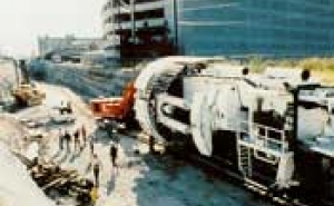
S A Healy chose to excavate the running tunnels using a refurbished gripper type Robbins TBM which achieved record breaking TBM excavation rates of up to 500 m/week in the good quality Austin Chalk (Fig. 1). After launching the TBM in November 1992, excavation of the two 5 km long x 6.5 m diameter running tunnels was completed in early January 1994, the second 5 km long drive being completed in just over four months.
Support behind the TBM comprised systematic bolting using four 3 m long fully epoxy resin bonded rebar dowels in every 1.5 m advance of the 6.5 m diameter tunnel. This is followed by a 50 mm layer of reinforced shotcrete. On exposure, the Austin Chalk is highly susceptible to deterioration and weathering. Its moisture dries quickly causing large shrinkage cracks which reduces the limestone's natural integrity. The contract documents therefore require that exposed surfaces be sealed within 24 hours of excavation. During excavation of the running tunnels and to avoid spraying shotcrete over the TBM equipment, Healy chose instead to clean the rock surface with high pressure water and seal it within the specified 24 hours with a clear sodium silica or 'wafer glass' product. The finishing 50 mm layer of shotcrete was then applied as a second pass operation.
For its shotcreting requirements, Healy has used the wet rather than the dry mix method and has used 10 lb/yd3 of collated, fibrillated polyfibre reinforcement instead of the more usual wire mesh or steel fibre reinforcement.
Healy is said to have chosen the polyfibre shotcrete option for several reasons. It is corrosion proof and slightly more cost effective than steel fibre. It is easier and less labor intensive to use than wire mesh and it eliminates the need for a protective coat of plain shotcrete required when using steel fibre in conjunction with a plastic waterproofing membrane.
To take advantage of the TBM's advance rates, Healy decided to complete the two running tunnels through the station areas first and subsequently enlarge these using roadheaders to create the station platform caverns. In these areas, fiberglass dowels were used in the TBM drives instead of rebar. Meanwhile top down excavation of City Place Station started with the installation of slurry walls through the overburden to allow blind hole drilling of the four ventilation shafts and excavation of the escalator declines. Once into the Austin Chalk, roadheaders again made quick work of carving out the necessary chambers and edits.
By early August 1994 all excavation on the contract had been completed. By November 1995 the lining work in the tunnels and installation of the final cast-in-place concrete lining in the station had been achieved. DART's 20mile starter system remains on schedule for an opening date in late 1996. At that time, the NATM approach for the underground works will have made a significant contribution to a more economic realization of the project.
3. NATM RATIONALIZATION
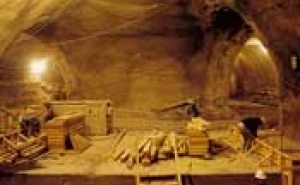
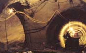
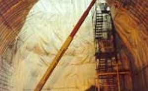
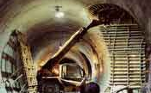
NATM savings over more traditional underground design excavations are accrued principally through the different material requirements and time saving devices incorporated in the NATM philosophy. Where steel arches and thick walled, heavily reinforced concrete linings might have been used in a more traditional design, the NATM approach in Dallas is based on more spacious openings in the stations and more cost effective use of materials for shotcrete lining, rock support (Fig. 2, 3) cast-in- place concrete inner lining and long term maintenance. Plastic waterproofing membrane and drainage system in the station and public access structures is another cost effective element readily identified with the NATM concept and one which is known to provide significant long term maintenance and operating savings (Fig. 4).
This optimization of design is perhaps the most easily appreciated characteristic of the NATM. Through a series of comprehensive calculations using a number of possible variables, the size of openings, excavation sequences, size and advance of headings, the shotcrete and cast-in-place concrete lining requirements were specified. This process refines the design, eliminates traditional conservatism and optimizes support requirements closer to statutory safety factor limits.
The large underground openings in Austin Chalk present a formidable challenge logistically. Excavation of the station chambers took place within 26 m below the road deck of the new North Central Expressway highway cutting and within 35 m of the adjacent foundations of the multistory City Place tower block (Fig. 5).
The large 18 m x 18 m x 7 m highdome- vaulted mezzanine level chamber is believed to be one of the largest free span manmade caverns constructed in medium soft rock in the U.S. to date. The crown of the chamber lies some 14 m below the deck of the depressed highway and only 8 m beneath the chalk interface with the 6 m deep overburden of waterbearing sands gravels and other alluvial deposits. Its excavation was further complicated by the full wallsized junctions of passenger access edits on all four sides.
The two 146 m long x 72 m2 station platform tunnels (Fig. 6) are just 24 m apart (center line to center line) and involve several cross edits of various sizes with relatively narrow pillars of chalk between. There are several overhead junctions with ventilation shafts and access points and the main escalator shaft on its 1 in 7 (30 ) decline leaves an intermediate pillar of only 4 m with the running tunnel at the narrowest point.
This called for a careful workmanship and adherence to design requirements to assure success of the excavation. Any deviation could cause excessive ground movement and settlement damage to surface and subsurface structures resulting in costly, time consuming repair measures adding to contract cost and delaying the schedule. This encompasses risks to the owner and had significant influence on project budget items such as insurance and damage compensation to third parties. In addition to City Place tower, several other structures are influenced by the works. These include a recently completed storm water drainage tunnel needed in association with the new depressed highway project, several cross road bridges over the new highway and many subsurface supply lines, all of which are sensitive to excessive ground movement. These concerns are covered by another from the NATM concept inseparable element. The City Place excavation contract includes a conservative estimate of $750,000 of geotechnical instrumentation.
4. INSTRUMENTATION & MONITORING
4.1 Purpose of instrumentation
4.1.1 Verification
The design process behind the NATM is a semi-empirical one. While sophisticated calculations which are typically based on the use of numerical models (i.e. finite-element, difference methods) traditionally form an integral part because of their ability to take into account soil structure interaction, experience that flows into the design product plays also a significant role. The calculations are based on assumptions on ground conditions involving geologic and hydrologic conditions and derivation of the geotechnical parameters which form the basis of the design. A characteristic element of the NATM (also one of the driving factors in the development of the NATM concept) is optimization of ground support and therefore economy. By taking advantage of the self supporting capability of the ground, further enhancing it by cross sectional shape, adjusting excavation sequences, and using pre- support measures often a much lighter support is achieved as compared to traditional methods. Naturally it is the Engineer's desire to verify the design assumptions by comparing actual behavior of ground and structure with the predicted behavior made on the basis of assumptions. Verification of predicted behavior by monitoring gives the engineer and the client confidence in his project and substantiates cost savings of this optimized design.
4.1.2 Economy
It is true to say that the rationalization of the NATM design during construction can be a difficult concept to utilize particularly in more complex structures and those of limited length or confined excavation. It is more common and easier to vary support specifications in line tunnels where the alignment passes through different types of ground and the economies of doing so are more substantial. In station construction, the excavations are often too complex and limited. Therefore the design typically foresees only one type of support specification for a particular stretch of station segment such as station tunnel, cross edits, escalators, etc. which are prescribed with a specific excavation and support sequence. However, even if not prescribed by the contract especially relaxations with regard construction sequence, quantities of material built in, etc. may be arranged in the field to benefit both the contractor by increasing advance rates and the client as well.
If improvement can not be achieved because of ground conditions the use of geotechnical data maintains its role at the opposite end of the spectrum, namely to warn of the need to apply extra support or change the sequence to meet deteriorating ground conditions remains vital. By warning of potentially damaging situations they provide the contractor with the chance to carry out necessary remedial action before any damage occurs, thereby ensuring safety of his operations, adjacent surface and subsurface structures and the public.
4.1.3 Legal Aspects
While verification and economy certainly form the main cause for instrumentation a frequently neglected reason is its legal aspect. Especially in urban areas as here in Dallas and even more significant when dealing with soft ground tunneling the impact on utilities as well as nearby subsurface an surface structures has to be known to deal with the possibility of abutter's claims such as cracks on buildings, damaged utilities, etc. With the availability of instrumentation data at typical and critical locations the history of ground behavior can be assessed. Knowledge of 'es is' conditions prior to tunneling, development of monitoring data during tunneling in the area of influence (instrument reading vs. time and tunnel progress) and observation of the instrument for a sufficient time after the excavation has passed by form a complete history case. By this history possible claims on structure damage can be objectively analyzed and the responsibility for cause reasonably assigned.
For the assessment of 'as is' conditions prior to tunneling nowadays more and more photographic or video film documentation techniques are being utilized. With video film documentation a vast information can be stored at relatively low cost. Only raw film material is required that becomes part of escrow documents and has to be analyzed only if disputes over damages actually occur. The objective analysis of instrument monitoring has to be accurate and reliable. Skilled personnel is needed for installation, readings and immediate interpretation as well as documentation.
4.1.4 Responsibility
Once installed, the monitoring, interpretation and subsequent reaction by the contractor can be organized in various ways. Ideally, installation, monitoring and data correlation should be handled by an competent firm working for the owner and independent of the contractor. The data should then be made available to all parties for prompt interpretation and response. Mainly because of construction safety reasons however, it is common practice that the contractor is responsible under a billed item in the contract, to procure, install and monitor the instrumentation.
The often found resistance to properly maintain and read instruments because it hinders and slows down the progress, is well understood. Many contractors will try to reduce the quantity of the specified instrumentation, mainly because of their cost but also because of the interruption in the excavation programme caused by their installation in the first instance and by their continuous monitoring as excavation progresses. An incentive to maintain, monitor and process instrumentation readings should be made through a unit price schedule with payments issued for properly maintained instruments and readings according to specified frequency only.
4.2 Instrumentation at City Place
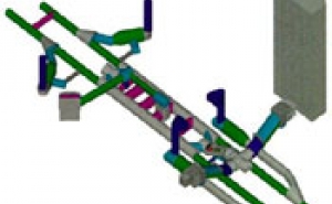
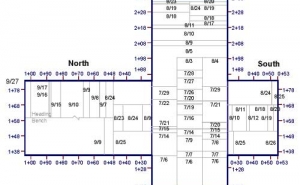
While there are several sets of instrumentation along the route of the running tunnels in Dallas, the majority by far are installed at the City Place Station area. Figure 5 displays City Place Station and its running tunnels which lie below the new depressed North Central Expressway and link directly into the basement of the adjacent City Place office block tower. Also shown is the layout of instrumentation.
Contract documents specify quantity of instrumentation, location of instruments and its reading frequencies. A particularity of the NC-1B contract was that it was bid based on a preliminary design completion level. The bid price was then adjusted through incorporated contingency amounts to account for the final design requirements. Following contract negotiations S A Healy was made responsible for the installation, maintenance and reading of the instruments. The data were then processed by Dr.G.Sauer Corp. in cooperation with Stone & Webster, the owner's construction manager.
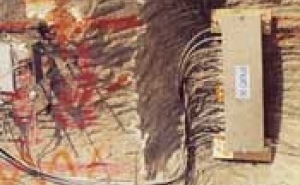
At City Place the instrumentation is of two principal types those installed from the surface well before excavation begins and those installed as part of the excavation process. Surface installations include multiple point borehole extensometers, inclinometers and a comprehensive array of surface reference markers and survey points. From within the tunnel and as the excavation progresses ground load cells, concrete pressure cells, and convergence cross section markers or diodes were installed. Load and pressure cells are very flat devices that are designed for monitoring of the confining stresses acting within the shotcrete lining (concrete pressure cells) as well as the radial stresses, acting normal to the tunnel lining (earth pressure cells, Fig. 7).
Obtaining the optimum benefit of geotechnical instrumentation on any project depends significantly on the durability, reliability and accuracy of the instruments them selves, the quality of workmanship during the installation, and the practicalities of taking the readings when necessary. The quality of instrumentation today is such that there is now a marked reduction in the failure rate of installed instruments. The accuracy of installation and interference by other construction equipment however can be a problem.
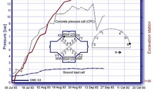
Those installing the instruments must be aware of exactly where and how each different device must be installed for it to function correctly and to avoid the potential for inconsistent or misleading readings. Also, unless installed with adequate planning and attention, sets of instruments can become redundant by being hidden by ventilation ducting, for example, or because their position isinaccessible for monitoring with the correct equipment such as theodolites. If all parties play together well, instrumentation results can be achieved as those shown in Figure 8.
Of the vast quantity of data gathered on the City Place excavation contract, one of the most critical sets were those recorded during excavation of the large mezzanine level chamber. Figure 8 displays the development of stresses in the shotcrete lining and ground stresses on the lining as a function of time at cross section 'XX' in the mezzanine cavern. reading the curve remains asymptotic and with about constant values. Also incorporated in the graph is the progress of excavation curve.
Due to the complex arrangement of excavations that took place within the mezzanine cavern the instrumentation was supplemented by Figure 9 which indicates the state of progress versus time. Correlation of excavation and monitoring results clearly indicates the steady stress increase in the cells until about 25 August (Figure 9, excavation face at Sta. 0+48 in the north drift). At that time the excavation had been completed in the mezzanine cavern and the stresses in the surrounding ground redistributed to an equilibrium condition. Following this date the excavation being at a distance of some Q cross section diameter away does not impact the stress condition in ground and lining at the instrument cross section. Apart from an apparently erroneous reading the curve remains asymptotic and with about constant values.
5. SUMMARY
As is the case on all projects, there have been differences of opinion among the parties, however, these have been resolved quickly and amicably and on site. Partnering was adopted at the outset as a contract management concept and there is a disputes review board in place to handle more serious situations should they arise. Currently a final, comprehensive instrumentation and monitoring report is being prepared on ground and lining behavior during excavation, and impact on adjacent surface and subsurface structures.
ACKNOWLEDGEMENT
We would like to thank Mr. Vladimir Goubanov of S A Healy who provided the isometric view of City Place Station in Figure 5.
REFERENCES
- Bauer, E., Gall, V., Sauer, G., June 1994. Computer Calculations Speed Tunnel-Lining
- Design, Civil Engineering Magazine.
- Einstein, H. H., 1979. Observational Methods in Tunnel Design and Construction, 3rd Annual
- Conference on DOT Research Development in Tunneling Technology.
- Sauer, G., 1980. Tunnel Instrumentation and in-situ Observation, Tunnelling and Geology Conference London, Proceedings, Chapter II.
- Sauer, G., Gall, V., Bauer, E., Dietmaier, P., 1994. Design of Tunnel Concrete Linings Using Capacity Limit Curves, 8th International Conference on Computer Methods and Advances in Geomechanics, Morgantown, WV, Proceedings, Vol. 3.
- Pacher, F., Sauer, G., 1980. Gedanken zur Auslegung von Tunnelausschreibungen und zum Stand der messtechnischen Bauwerksuberwachung [Review and Interpretation of Bid Documents and State of Instrumentation and Monitoring], Rock Mechanics, Suppl. 10, Springer Verlag, Vienna.
- Vavrovsky, G-M., October 1995. NATM: Geomechanical Principles Explained, Tunnels & Tunnelling Magazine.
- Wallis, Sh., May 1992. Dallas Area Rapid Transit, World Tunnelling Magazine.
