You are here
Infrastructure Upgrade through Innovative Tunnel Rehabilitation
Rapid Excavation and Tunneling Conference, New Orleans, LA, June 2003
ABSTRACT
With obvious signs of deterioration, the double track, historically registered Bergen Tunnels as part of the commuter rail system in New Jersey waited for rehabilitation for a long time. Serious water infiltration not only caused operational and safety hazards for the electrified rail line but also deteriorated and structurally compromised the tunnel lining. An innovative rehabilitation program was developed to enlarge the tunnel and to provide a new waterproofing system and final lining. For the rock excavation and support New Austrian Tunneling Method (NATM) principles were utilized, while watertightness was achieved by installing a PVC membrane waterproofing system followed by a reinforced cast-in-place final lining. Experienced on-site supervision generated additional savings during construction by streamlining support elements based on geologic conditions encountered.
TUNNEL HISTORY
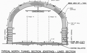
The Delaware, Lackawanna and Western Railroad began construction of the Bergen Tunnel north tube from the east in 1873. Excavation was completed in 1876, with rail traffic initiated in 1877. After about a third of the tunnel’s interior surface was found to be insecure it was decided to install a 0.60 m (2 ft) thick multilayered brick arch on stone masonry sidewalls in specified locations, delaying the official opening until 1887 (see Fig. 1). Construction costs for excavation and support of the tunnel and the lining was estimated as $905,000 (Taber 1998). With the increase in rail service it became necessary to bore a second tube south of and adjacent to the north tube. It was completed in 1908.
Both tubes are approximately1,340 m (4,400 ft) long and 8.2 m (27 ft) wide, and traverse the southern reaches of the Palisades, known as the Bergen Hill in the Heights section of Jersey City, NJ. The south tube was completely concrete lined. The original north tube included one major open cut and five air shafts. During construction of the south tunnel a second full width air shaft was constructed, thereby breaking the tunnel into three sections, so the smoke from the steam and later diesel trains could freely escape. Infiltrating water from the Jersey City Reservoir created a serious challenge during construction of the tunnels (New York Times 1876). In and around 1930 the tunnel was modified to incorporate DC electrified catenary service. The tunnels were further upgraded to AC electrified service around 1984.
PROJECT BACKGROUND
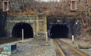
After years of electrified service, especially the north tube began experiencing increased water leakage, which became problematic during winter months, creating power interruptions. Maintenance and removal of icicle formations became a regular activity. Attempts to divert the increasing amount of water intrusion with available methods of grouting and diversion were unsuccessful. In the mid 1990’s design was initiated by the owner New Jersey Transit to completely waterproof the north tunnel and also improve the situation in the south tunnel (Fig. 2).
OPERATIONS & CONSTRUCTION PLANNING
The original design approach was to attempt rehabilitation work under traffic. After much discussion it was determined that to best complete the project successfully, removal of service was the only option. Once the decision to rehab the tunnel in an out of face manner was made, several enhancements to the system were added. Improved lighting, safety walk, emergency egress points, fire and life/safety access, emergency communications and powerful smoke evacuation systems were included in the final package.
To accommodate this new approach, modifications to the existing passenger operations were necessary. The seven rail lines approaching via eight tracks had to be diverted into the operating south tube during construction. To accomplish this, critical decisions regarding levels of service and passenger impact had to be made. Approximately 12 trains per day were eliminated. The majority, however, were adjusted by only several minutes on each end (arrivals and departures) to manage the two track bottleneck. This presented its own set of concerns. To remedy any delays resulting from a potential breakdown within the operating tunnel, standby engines were maintained throughout the reconstruction duration to assist the train in making its final destination.
GEOLOGICAL SURVEY AND MATERIAL TESTING PROGRAM
A comprehensive inspection, survey and material testing program was performed to assist in the condition evaluation for the tunnel structures, to locate all water intrusion areas, and to define the rock surface behind the tunnel lining. Photographical scanning with laser equipment and infra-red thermography as well as a detailed structural, mechanical, electrical, and systems inspections provided large amounts of data as basis for the design.
A test boring program was developed to provide information about the rock and brick lining. Twelve borings were taken from within the tunnel during night work windows as permitted by New Jersey Transit, which allowed for approximately three hours of productive work. Cores were logged in the field, and again in the laboratory after further review. Percussion probe borings were conducted to determine the thickness of the brick lining, presence and size of voids and the nature of the back packing material. Seven borings were made from the surface using the rotary wash method to determine the rock line elevations.
The rock is described as varying between extrusive basalt with columnar jointing, and intrusive diabase. Filled discontinuities and evidence of shear and displacement joints were found throughout the tunnel. Test results for the brick lining showed that some bricks had deteriorated severely over time mainly due to environmental conditions while the mortar and stones of the sidewalls were performing well. Overall, the tunnels were rated to be in fair to poor condition with desperate need for rehabilitation.
STRUCTURAL DESIGN APPROACH
Four alternative rehabilitation schemes were developed, ranging from structurally improving the brick lining and grouting behind the lining to a full replacement of the lining, installation of a waterproofing membrane and cast-in-place final lining. The limited clearance of the existing brick lining and changed requirements for future rolling stock as well as resistance against seismic loads and a minimum service life of 50 years were key factors for evaluating these alternatives.
Inspired by the NATM-type rehabilitation of the Lehigh Tunnel No. 1 near Allentown, PA (Mergelsberg 1996) and the Berry Street Tunnel in Pittsburgh, PA, New Jersey Transit decided to pursue a similar concept for the rehabilitation of the Bergen Tunnel. There, the contractor together with their design consultant, the Dr. G. Sauer Corporation, successfully proposed an excavation and support scheme that greatly benefited owners as well as the contractor in terms of cost and schedule (Garrett 1997). The Dr. G. Sauer Corporation was therefore asked to join the Bergen Tunnel design team led by URS/Sverdrup JV to implement a cost and schedule effective design in accordance with the established criteria.
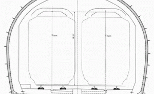
After review of all information a tunnel cross section was developed that accommodated the clearance requirements for train operations, systems, and fire and life / safety equipment (see Fig. 3). Based on the findings of the geotechnical investigation program geotechnical profiles were generated to define the limits for the Excavation and Support Types I, II, IIIA and IIIB. Type I represents competent rock, where support comprises of lattice girders 1.5 m (6 ft) on center and an initial shotcrete lining with a thickness of 0.15 m (6 inches). For Type II grouted rock dowels are added in the arch area. For Types III the distance between lattice girders is reduced to 1.2 m (4 ft) and the advance of the brick lining removal ahead of the support installation is reduced. Application of Types III is expected to be limited to portal and shaft areas. Additional horizontal grouted spiles provide support for loose material behind the brick lining in these areas.
For immediate support after excavation and for protection against falling rocks the initial reinforced shotcrete lining in accordance with NATM was foreseen. An instrumentation and monitoring program was designed within the tunnel and on the surface to observe, monitor and interpret all movements during and after excavation. To comply with the main purpose of the rehabilitation, namely creating a watertight structure, the PVC membrane waterproofing system was recommended. An open system was suggested, where the membrane is terminated at the invert and the water is collected and drained by horizontal 0.15 m (6 inch) diameter perforated Raudril drain pipes. These drain pipes connect to the 0.3 m (12 inch) diameter track drains in the center of the tunnel every 15 m (50 ft). Great emphasis was given to the requirement that the entire drainage system is maintainable and can be cleaned periodically. Cast-in-place concrete was used for the invert slab and final lining. Fire protection criteria required that all conduits are encased in the concrete lining.
For the structural analysis two-dimensional finite element models and wedge failure models were calculated to determine the structural and reinforcing requirements. Two finite element models with pre-defined discontinuities were developed using the program ABAQUS. All sequences and load cases were analyzed, including the excavation and support steps, wedge failures and seismic loadings. Results of the models confirmed the initial assumption for the required lining thickness of 0.3 m (12 inch).
EXCAVATION AND SUPPORT
The construction contract was awarded to the joint venture of Merco /Obayashi for $56.4 million. Construction started in July 2001 and is expected to be completed by March of 2003. To stay within the very tight schedule the contractor was required to work 24 hours per day, five days a week, and advance multiple faces simultaneously. A summary of the schedule and typical quantities is shown in Table 1.
Table 1. Schedule and quantities.
|
Unit |
Start Date |
End Date |
Quantity |
|
Overall Schedule |
July 9, 2001 |
February 2003 |
- |
|
Rock Excavation |
August 16, 2001 |
April 30, 2002 |
8,860 m3 |
|
Shotcrete |
August 2001 |
January 2003 |
8,540 m3 |
|
PVC Waterproofing |
March 26, 2002 |
November 15, 2002 |
29,330 m2 |
|
Tunnel Final Lining |
April 23, 2002 |
December 17, 2002 |
19,800 m3 |
|
Invert Slab |
October 14, 2002 |
January 24, 2003 |
3,290 m3 |
|
Electrical Conduits |
- |
- |
22.5 km |
Work started at the portals. Because the portals are historic, they had to be carefully dismantled, preserved, and reconstructed to avoid damage to any of the rock blocks and carvings (Burke 2001) before the work in the tunnel could proceed.
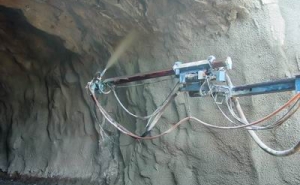
For the excavation of the brick lining and the grout behind the brick drill and blast as well as hydraulic hammers were used, rock of the tunnel crown and invert was excavated by drill and blast. Drilling was carried out by twin-boom rubber tired jumbos. Blasting in the middle of a populated area and only 7.6 m (25 ft) away of an active commuter rail line has many restrictions. The contractor was only allowed to blast between 8:00 a.m. and 6:00 p.m. and in coordination with NJ Transit commuter rail traffice, which left the mucking and shotcreting operation for night hours (Sedjo 2001). Shotcrete was applied with a Meyco® Spraymobile, a robotic self contained unit supplied by Master Builders Technologies (MBT), whose experts also provided training for operating and maintaining the Spraymobile. Despite the training it took the contractor some time to become effective with this robotic application. Application rates between 764 m3 (1000 cubic yards) and 1,147 m3 (1,504 cubic yards) wet shotcrete could be achieved with the robotic arm per week of full operation (Garrett 2002). Rebound was calculated to be in the range of 3% to 5%, which is considered very low (see Fig. 4).
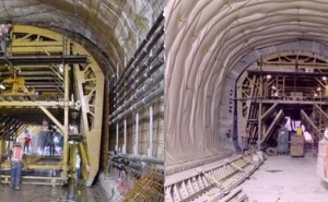
After the shotcrete lining surface was accepted by the inspection team comprised of New Jersey Transit inspectors and supported by Dr. G. Sauer Corporation expert advisors, the PVC membrane waterproofing system was installed. A geotextile is mounted with PVC disks as protection and drainage layer between shotcrete and PVC membrane. Then, the PVC membrane is hot-welded to the PVC disks to provide a penetration free fixation. Double-seem welds are used to weld the membrane sheets together. All seems were tested with air pressure for air and therefore watertightness. BA anchors were used to mount reinforcing steel before the formwork was put in place and the cast-in-place lining poured in 84 15.24 m (50ft) sections with two traveling forms (see Fig. 5).
SITE DECISIONS
Knowledgeable and experienced supervision staff, designers and contractor’s representatives on site are essential for successful change order and value engineering negotiations. Motivated by potential schedule and cost savings the contractor proposed to eliminate lattice girders in sections of competent rock and apply shotcrete only to seal the surface. Despite the many overbreaks the amount of shotcrete could be reduced substantially because the voids did not have to be filled with shotcrete. The voids were filled with cast-in-place concrete instead during the final lining installation. Approval of the proposed change depended on the review of monitoring data, analysis of geological and geotechnical information gathered during excavation and the review of the structural computations based on the changed parameters. The change was approved and therefore saved cost for both, the owner and the contractor, and accelerated the construction schedule.
This is one example of knowledge and experience based decision making that benefited all involved parties. It was possible due to the experts on the team who understood the interrelation of construction activities, geology, monitoring, and design assumptions.
REFERENCES
- Burke, J., 2001, "Bergen Tunnel Rehabilitation", World Tunneling, pp. 83ff.
- Engineering News, May 1876.
- Garrett, R., 2002, "Bergen Revisited - Contractor Takes Lead in New Technologies", World Tunneling March 2002, pp. 481ff.
- Garrett, R., 1997, "Pittsburgh Berry Street Rebuild", North American Tunneling, June 1996.
- Mergelsberg, W., Gall, V., Sauer, G., 1996, „Achieving dry cut-and-cover stations - A membrane based waterproofing system for underground structures", North American Tunneling Conference 1996, Proceedings, pp. 353ff
- New York Times Article, "The Jersey City Reservoir Leaking", March 6, 1876.
- Jersey City Evening Journal, "The Cave-in at Shaft No. 5", March 6, 1876.
- Sedjo, A., 2001, "Century-Old Tunnel Brought Up-To-Date", TBM - Tunnel Business Magazine, December 2001, p. 46.
- Taber, T., Taber, T., 1998, "The Delaware, Lackwana & Western Railroad in the 20th Century", Steamtown Volunteer Associates.
