You are here
Rehabilitation of the Big Walker Mountain Tunnel in Bristol, Virginia
AUA Conference
North American Tunneling 2004 Conference and Exhibition
Atlanta, GA
ABSTRACT
The Big Walker Mountain Tunnels are a pair of two-lane highway tunnels built in the late 1960’s and early 1970’s and are operated and maintained by Virginia Department of Transportation (VDOT). Due to their age and condition VDOT contracted TAMS an Earth Tech Company to provide a structural rehabilitation design for the tunnels. The design included replacing tiles, railings, curbs, cleaning the drainage system and grouting the ceiling slab as well as repairing areas of the tunnel lining that were leaking. The Dr. G. Sauer Corporation (DSC), as a specialty subconsultant to TAMS, provided a tunnel lining and drainage rehabilitation alternative to the typical rehabilitation grouting. The design has the advantage that it will not adversely impact the existing drainage system unlike typical grouting operations. The key to the design is under-standing the four main principals of rehabilitation which are explained herein. This paper will explain the history of the tunnels, the tunnel lining and drainage rehabilitation.
1 INTRODUCTION TO THE TUNNELS
1.1 History
In the 1950’s when the Interstate Highway concept was passed into law, it included a “Great Lakes to Florida” route. One of the final segments of this link was the I-77 segment connecting I-77 in West Virginia to Virginia’s I-81. This highway includes 2 pairs of two-lane horseshoe-shaped tunnels; one of which is called the Big Walker Mountain Tunnels and is located in rural Bland County in southwestern Virginia. The design for the Big Walker Tunnels and approaches was developed in the 1960’s by Singstad & Kehart consulting engineers of New York City who employed a young tunnel engineer that would nearly 40 years later review the tunnel rehabilitation design as a Senior Tunnel Engineer of Federal Highways, Anthony S. Caserta, P.E.
1.2 Tunnel specifications
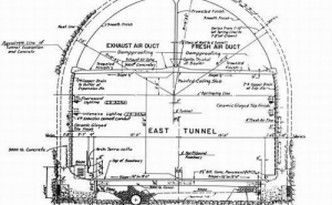
The Big Walker Mountain Tunnels, each with a length of 1289 m (4229 feet), slope upwards towards the north on a 3.5% grade and are separated horizontally by 8.2 m (27 feet) of ground. Inside, each of the tunnels contain two, 4 m (13 foot) wide traffic lanes, an 80 cm (2.6 foot) wide sidewalk which houses utilities and a 50 cm (1.5 foot) wide ledge (see Fig-ure 1). The roadway has a 5 m (16.5 foot) vertical clearance above which is a 25 cm (12 inch) thick ceiling slab. The area above this slab is split in half with a vertical cast-in-place concrete wall and pro-vides the exhaust and fresh air ventilation ducts. There are two cross passages connecting the tunnels with a clearance of 1.8m wide by 2.1 m high (6 feet wide by 7 feet high).
1.3 Cut-and-cover vs. tunneling
The tunnel and approach design included a 300 foot deep open cut through the Little Walker Mountain which consisted of over 3.8 million cubic meters (5 million cubic yards) of material to be removed. The engineer’s estimate to cut through the Big Walker Mountain revealed that the cut would be 150 m (500 feet) deep and would require the removal of nearly 9.2 million cubic meters (12 million cubic yards) of material. It was then estimated that to tunnel through the Big Walker Mountain that only a fraction of material would have to be removed. The design anticipated that the portal areas would be constructed with excavators through soft and mixed face ground and the majority of the tunnel length would be drilled and blasted. Actually, 249,000 cubic meters (326,000 cubic yards) of rock were removed from the tunnel and about 765,000 cubic meters (a million cubic yards) of soil were removed from the portals and moved into the nearby approach fills. Overall the tunneling operation created just over 11% of the volume of material as the open cut.
The construction for the 37 kilometers (23 miles) of roadway, bridges and tunnels cost nearly $50 million and was divided into numerous contracts. The tunnel contract was awarded to C.J. Langenfelder & Son, Inc. of Baltimore, Maryland in September of 1967 in the amount of $22.6 million. After the tunnels and the highway were dedicated on June 23, 1972 and opened, the traffic volume was estimated at 5,600 cars per day (VDOT 1975). Now more than twenty years later, the traffic has increased to 28,000 cars per day (VDOT 2002). With so many motorists using the tunnels combined with the unusual facts that motorists are permitted to change lanes while inside the tunnel and that there is no restriction on hazardous material hauling, it is extremely important to keep up with normal maintenance issues.
2 TUNNEL DESIGN AND CONSTRUCTION
In order to understand the problems affecting the tunnel today we first had to understand how the tunnels were constructed. The majority of the drill and blast tunneling was done through competent rock consisting of Sevier shale which was yellow and slightly calcareous to sandy overlain with Clinch sandstone which was coarse. The design prescribed five construction methods as listed below:
- Roof bolts with channels.
- Concrete and grouting of rock seams.
- Structural steel support without lagging but blocked against rock, concrete and grout
- Structural steel support and 1.8 m (6 foot) steel lagging channels, dry stone packing to be grouted beyond the lagging
- Structural steel support and 1.8 m (6 foot) steel lagging channels, concrete and grout beyond the lagging.
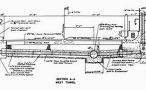
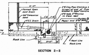
When seams were encountered, they were to be thoroughly cleaned out, grout and weep holes drilled, and the seam caulked then grouted. After the rock was supported, a continuous, reinforced con-crete footing was constructed onto which a 51 cm (20 inch) thick reinforced concrete lining was cast in 11.4 m (37.5 foot) sections. At the end of every section is a 10 mm (3/8”) transverse expansion joint which consists of a 23 cm (9”) wide PVC waterstop, 10 mm (3/8”) premolded cork joint filler then a continuous formed open joint drain in which water is collected. The joint drain is formed with half of a 3” asbestos cement pipe at the end of one pour and half of a 10 cm (4”) asbestos cement pipe left in place in the adjacent pour. Each open joint drain has a 7.6 cm (3”) cleanout above the sidewalk and ledge so the water from the open joint drains is deposited into a 10 cm (4”) cast iron drain pipe on both sides of the tunnels. The 10 cm (4”) drain pipe carries the water longitudinally about 1.8 m (6’) to a 1.2 m × 0.9 m (4 foot × 3 foot) pocket of gravel where the water is fil-tered before it flows through a stainless steel screen and into the 15 cm (6”) transverse drain (see Figure 2). The 15 cm (6”) drain flows to the 38 cm (15”) perforated clay pipe that runs longitudinally through the center of one lane of the tunnel (see Figure 3).
3 REHABILITATION
3.1 Inspection
Vincent F. Schimmoller, deputy executive director of the Federal Highway Administration (FHWA) is quoted as saying “We can’t simply design and build tunnels and expect them to take care of themselves. We must apply sound engineering and business principles to maintain our tunnels.” (Botelho, 2001)
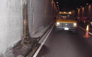
In July 1986, a structural inspection was performed which located and documented numerous cracks in the tunnel lining and expansion joints that were leaking and had caused deterioration to areas of the tunnel lining and finishes. In fact during the winter, the active leaks frequently caused icy conditions near the tunnel portals therefore it was necessary for the tunnel maintenance department to temporarily install heat tape to active leaks to prevent freezing. As a result of leaks that have existed for a period of time, adjacent wall tiles were delaminated (see Fig-ure 4), the roadway pavement had deteriorated and formed potholes, the ceiling slab had deteriorated in areas and rebar was exposed, all of which posed a safety hazard to the public. There was a location above the ceiling slab where the pipe that drained water from the ceiling slab was obviously clogged and created a pond on the slab. This water eventually made its way down the sidewall and resulted in de-laminated wall tiles and deteriorated concrete.
3.2 Chasing the water
Rehabilitation in the past consisted of crack and joint grouting with limited success. While some of the cracks dried up, some of the joint drains and gravel pockets were clogged with grout rendering the joints drains ineffective. Then within a year after the grouting was completed, new leaking cracks were detected so the grout was found to chase the water from one crack to an entirely new crack. An-other issue is cost. VDOT found the cost of a grouting operation with the intention of providing a dry tunnel was unpredictable because grouting was needed on a regular basis to dry up new leaks.
3.3 Development of a rehabilitation alternative
The Dr. G. Sauer Corporation approached VDOT regarding rehabilitation of their existing tunnels. After reviewing the inspection reports and videos and noting the typical problems encountered with grouting operations, DSC proposed a sound rehabilitation philosophy based on managing the water and provided examples of where the system had been implemented successfully.
3.4 Understanding the water
In order to properly design and implement the tunnel leak remediation, four questions have to be addressed.
- Where is the water coming from?
- How can the water be drained?
- How will the drainage system be maintained in the future?
- How to prevent water from freezing and clogging the drainage system?
3.4.1 Where is the water coming from?
Previous inspections of the Big Walker Mountain Tunnels documented that water was leaking through the existing expansion joints and through cracks in the lining. A large concentration of leaks was located within 120 m (400 feet) of the portals due to the geology and hydrology at tunnel portals.
The leaks located at the ceiling slab joint are typical to most tunnels built through rock in the 50’s through the 70’s as the tunnel lining was constructed in stages with a joint at the ceiling slab. Also, as grouting was performed previously at the expansion joint locations, the joint drain was clogged and water is making its way around the PVC waterstop and into the tunnel creating leaking joints.
It is important to intercept the water where it enters the tunnel either by drilling relief or collection holes and/or providing new joint drains.
3.4.2 How can the water be drained?
Above the ceiling slab, in the ventilation exhaust and fresh air ducts, it is sufficient to simply cover the leaking tunnel concrete lining with PVC membrane. This prevents the water from dripping onto and slowly damaging the ceiling slab and it also prevents icicles from forming and creating obstructions in the air ducts during the winter. On the ceiling slab where the slab meets the tunnel arch, a perforated drain pipe is wrapped into the PVC membrane and col-lects the leaking water (see Figure 4). A hole is drilled through the ceiling slab and a pipe is grouted in place. Then the pipe is connected to the drainage pipe in order to convey the water below the ceiling slab where it ties into the existing joint drain or into a new vertical drain as described below.
For tunnel lining leaks below the ceiling slab in joint locations, an area at the highest point of the leak must be opened and a section of the joint drain must be removed in order to test the joint drain to see if it is clogged. If the drain is not clogged then a funnel shaped mortar bed is formed around the top of the existing joint drain and 5 cm (2”) diameter in-clined holes are drilled into the rock. These collection holes will convey ground water to the opened section of the lining. The funnel shaped mortar bed will direct the water to the existing joint drain.
In the event that the existing joint drain is clogged, the joint drain must be removed to the top of the sidewalk or ledge and replaced with a 10 cm (4”) diameter pipe (see Figure 5). Due to the difficulty and cost of replacing the joint drain below the sidewalk and ledge, the existing joint drain must be capped and a slot for a horizontal drain pipe must be cut above the sidewalk or ledge to the existing gravel pocket. Although the drain pipe is termed horizontal, it is installed with a minimal slope to direct the water away from the joint and towards the existing gravel pocket. At the lower end of the future horizontal drain pipe, a 7.6 cm (3”) diameter side-wall diversion hole is drilled downward aiming for the existing gravel pocket. Care must be taken to document the location of the sidewall diversion hole as it may be necessary to drill from another direction to meet the diversion hole and drain the water if the gravel pocket is clogged (see Figure 6). The next step is to run water in the diversion hole to see if the water drains either into the gravel pocket or into the surrounding ground or whether the water leaks into the tunnel at any other locations. If the water drains properly then the vertical and horizontal drain pipes are installed. If the water does not drain, then an ad-ditional sidewall diversion hole can be drilled and tested. If the sidewall diversion holes fail the water test, then it is necessary to drill lateral diversion holes. This hole is drilled from the existing lateral drain pipe through the gravel pocket then the side-wall diversion hole is retested with water. The lateral drain pipes are located near each expansion joint however a manhole does not exist at every lateral di-version pipe. So it may be necessary to open the roadway in order to access the lateral diversion pipe. If the water added at the sidewall diversion hole does not communicate with the lateral diversion pipe, continue drilling additional sidewall diversion holes to meet the lateral diversion hole until the sidewall diversion hole passes the water test. Then install the vertical and horizontal drain pipes and connect with fittings to the sidewall diversion hole.
3.4.3 How will the drainage system be maintained in the future?
This is one of the most important questions. If the new drainage system clogs with sediment, etc. it is important that the owner can clean and maintain the system otherwise a new system will have to be installed and the old one goes to waste.
The new drainage system below the ceiling slab can be maintained by flushing water from the top of the vertical drain which is covered with an access panel and through the clean out located at the low end of the horizontal drain pipe which is also covered with an access panel.
Above the ceiling slab, the new drainage system can be maintained at the cleanout which is installed at one end of the waterproofed area and is covered with an access panel.
Drainage systems should be flushed on a regular basis to prevent calcification and sedimentation.
3.4.4 How to prevent water from freezing and clog-ging the drain system?
Even a clean drainage system can become clogged if water is permitted to freeze in the pipes. Therefore, all of the access panels that are covering the vertical and horizontal drain pipes as well as the area at the top of the vertical drain pipe where the collection holes drain, are thoroughly insulated. In the air ducts, the PVC membrane is also protected with rigid insulation and in addition, a heating strip is in-stalled in the drain pipe that is wrapped in the membrane.
A system similar to this was successfully installed at the Lehigh Tunnel No. 1 in Allentown, Pennsyl-vania and at the Felbertauern Tunnel in the Austrian Alps. Constructed through rock in the late 1950’s, the Lehigh Tunnel No. 1 had numerous cracks and leaks that resulted in formation of significant icicles in the winter (see Figure 7). The Felbertauren Tunnel was built 10 years later and suffered the same problems. Since the drainage rehabilitation to the Lehigh and Felbertauren Tunnels nearly 9 and 19 years ago respectively, the tunnels are remarkably drier which extends the life of the tunnel structure and fixtures.
4 REHABILITATION CONSTRUCTION
Due to the reduction in government funds which is common to all DOTs nationwide, rehabilitation of the Big Walker Mountain Tunnels has not been advertised for construction at the time this paper was written. We look forward to updating this paper in the future with the contractor’s experiences and recommendations.
5 CONCLUSION
Old tunnels don’t have to leak nor do they have to be grouted and regrouted over and over to eliminate leaks. In the past grouting was performed on many leaking tunnels with limited success. Some leaks may be eliminated while new leaks appear later. Also it is difficult to predict the cost of a grouting operation therefore the cost for the rehabilitation is an open ended question mark for which funding becomes very difficult. It is better to work with the water than to fight the water by understanding where the water is coming from and providing a drainage path for the water that is maintainable in the future and that will not freeze. The simplicity of this rehabilitation method is that it only has to be performed once for success.
It has been said that Bland County is the only county in the US that you enter through a tunnel (Big
Walker Mountain Tunnel) and leave through another tunnel (East River Mountain Tunnel. In the future, after the rehabilitation of the Big Walker Mountain Tunnels has been completed, one entrance will be significantly drier and safer. Fortunately, for the client, the rehabilitation design can be easily modified and adapted for the tunnels exiting the County as well.
6 AKNOWLEDGEMENTS
Thank VDOT and PTC for thinking outside the box and to Mr. Caserta for his assistance during the design of the tunnels and the tunnel rehabilitation.
7 REFERENCES
- Hanes, J.C., J.M. Morgan, Jr., The History and Heri-tage of Civil Engineering in Virginia, Virginia Sec-tion American Society of Civil Engineers, Part II, The Big Walker Tunnel, 1973.
- Mergelsberg, W., V. Gall, and G. Sauer, Achieving Dry Cut-and-Cover Stations, North American Tun-neling 1996. Proceedings of the International Con-ference on North American Tunneling ’96 and the 22nd General Assembly of the International Tunnel-ing Association/Washington, D.C. 21-24 April 1996. pages353-361 AA Balkema/Rotterdam/Brookfield
- Big Walker Tunnel Inspection videos performed by Parsons Brinkerhoff, 1986.
- Campbell, M. R., Pocahontas
- Commonwealth of Virginia Department of Trans-portation, Average Daily Traffic Volumes with Ve-hicle Classification Data on Interstate, Arterial and Primary Routes, 2002.
- Commonwealth of Virginia Department of Trans-portation, Average Daily Traffic Volumes with Ve-hicle Classification Data on Interstate, Arterial and Primary Routes, 1975.
- Botelho, F., A Light at the End of the Tunnel, U.S. Department of Transportation, Federal Highway Administration, Public Roads, Vol 65, No. 1, July/August 2001.
- Tunnel Vision


