You are here
Three pillars for an effective Waterproofing System for Underground Structures
North American Tunneling Conference, June 6-11, 2000.
ABSTRACT
Building dry underground space is of primary concern to its owner. It provides a friendlier and safer environment to the user and reduced maintenance efforts and associated costs to the operator. Achieving dry underground structures for public use in mass transit, vehicular tunnels but also for other non-private and private use is a multi-stage process which requires close cooperation between owner, planning engineer and contractor. Three distinct elements, referred to as pillars have been identified in building dry underground space: compatibility of the waterproofing system, thorough planning which goes hand in hand with other engineering disciplines designing the structure, and skilled installation combined with a thorough inspection.
INTRODUCTION
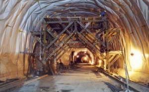
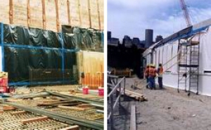
In the early 1980's, a new type of waterproofing system was implemented by the Washington Metropolitan Area Transit Authority (WMATA) on their Section B 10, Wheaton Station and running tunnels in Washington, DC. The system relies on the use of flexible membrane sheets (PVC) welded together to form a continuous, impervious layer and has produced a completely dry underground space. Based on its success, the system has since then been applied on various mined underground structures involving mass transit projects (i.e. Dallas Area Rapid Transit, Dallas, TX see Figure 1) and vehicular tunnels (i.e. Cumberland Gap Tunnels at the Kentucky, Tennessee border and the Lehigh No. 2 near Allentown, PA).
In the mid 1990's, WMATA pioneered a next step in seeking a reliable waterproofing system for their new cutand-cover construction at the Redline (Glenmont Station), the Mid City E-Route (Georgia Avenue Petworth and Columbia Heights Stations) and the Outer Branch Route (Congress Heights Station). Based on the success of the flexible system installed in bored tunnels implementation of this waterproofing in cut-and-cover construction appeared to be a logical consequence. An initial skepticism was overcome by a thorough analysis of variables involved. Backed up by case histories the three pillars for an effective waterproofing were determined. First, basic engineering principles have to be met; by concept the waterproofing system has to be compatible with the long-term behavior of the underground structure. This calls for special properties including continuity and long-term impermeability of the membrane and its capability to move quasi independently from the structure itself. Second, the planning for its implementation has to be thorough, ideally addressing most of the expected construction activities and problem areas already in the design. This being difficult, it was decided to enhance the waterproofing system by the so called 'sectioning system' which in case of leaks limits those to confined areas and allows for a targeted grouting for repair. Third, the installation has to be carried out by an experienced installer, inspected and supervised rigorously by an experienced and dedicated owner's representative.
With the three pillars in place WMATA was able to provide dry underground space for all of the four stations and associated cut-and-cover structures. A recent Federal Transit Administration web page information (Anon., 1998) reports on the vastly improved dryness of these underground structures criticizing (almost ironically) only the fact that the now dusty environment causes a more frequent change of rail car air filters. The Massachusetts Bay Transit Authority in Boston, MA has selected this waterproofing system for their new cut-and-cover construction and the installation is currently underway at sections of the new South Boston Piers Transitway.
Today the flexible membrane waterproofing system is not only successfully used in new tunnels and underground structures, but also incorporated into rehabilitation schemes of existing structures. Typical examples are the Lehigh No. 1 Tunnel near Allentown, PA, a highway tunnel built in 1957, as well as the 175 year old Thames Tunnel in London, UK, and the 135 year old Berry Street Tunnel in Pittsburgh, PA. These are structures where a flexible membrane waterproofing system was installed as an integral part of the rehabilitation to eliminate leakage and to ensure a dry tunnel environment for years to come.
WATERPROOFING SYSTEM - COMPATIBILITY, PLANNING AND INSTALLATION
Compatibility
When designing a waterproofing system, be it for a new structure or remedial reasons it has to be acknowledged that the structure and its surrounding ground constantly undergo a change over time. Tidal effects, stress redistributions, temperature and moisture changes, sedimentation, erosion and other factors continuously change the path of water in the geologic formation surrounding the underground structure. The structure itself exhibits changes in temperature, moisture and internal and external time dependent loadings which cause joints to open and close, creating new cracks, clogging up old ones, etc.
Knowledge of these facts led to the current, worldwide acceptance of membrane type waterproofing systems because membranes bridge the above-mentioned openings, dislocations and other strain related movements (Sauer, et. al., 1987). When adopting a membrane based waterproofing system the following minimum requirements must be met:
- The waterproofing system must be continuous.
- The membrane must be able to adapt to irregularities of surfaces it is attached to.
- The membrane must remain permanently impervious despite rheological or structurally caused movements (long term behavior of ground, temperature variation, vibration, or shrinking and creeping of concrete).
- The waterproofing system must be able to bridge small cracks in the construction surface. It must be able to absorb discontinuous stress-variations and to a certain extent provide sufficient tensile strength.
- The waterproofing system must be resistant to aggressive water, whether from natural sources or contaminated ground, and to biological attacks.
- The waterproofing system must be suitable for installation on damp and wet surfaces. It must be easy to handle and to install. Installation must be possible in large quantities with the help of reliable, mechanized and standardized methods at acceptable costs.
- The material must be self extinguishing in case of fire.
- It must be possible to check the waterproofing system for potential damage and to easily repair before placement of the concrete elements of the final structure.
- Provisions must be obtained for post construction remedial works
A waterproofing system that would satisfy these requirements was developed in the early seventies mainly in Switzerland and in Austria, combining a non-woven polypropylene geotextile and a high-polymer sealing membrane. The excellent results, obtained in the course of the construction of several important road tunnels in the Alps, consequently encouraged use of this new waterproofing system in subway and railroad tunnels and even shafts (Meggl, 1980).
Soon afterwards the method was adopted, together with the use of the New Austrian Tunneling Method (NATM) by most European Countries. In the mid eighties this waterproofing technique was first introduced in the U.S. at Section B10, Wheaton Station of the Washington Metropolitan Area Transportation Authority in Washington, DC (Martin, 1987). Since then the application of this system that relies on the geotextile and flexible plastic membrane has become standard in tunnel sealing applications in highway and subway tunnels in the U.S. (Irshad et. al., 1995).
While this membrane waterproofing system continued its successful "and increasing application in mined tunnel construction in parallel investigations were made into its use for other underground structures constructed by cutand-cover and open cut techniques. Soon European cut-and-cover tunnel approaches, underground parking garages, deep basements of sensitive public and commercial purposes and finally cut-and-cover subway tunnels and stations were successfully protected against the ingress of water using this waterproofing system.
Implementation of this waterproofing system in cut-andcover applications at Washington, DC Metro since the mid 90's has shown that dry underground space may be achieved in cut-and-cover structures as well (Mergelsberg, et. al., 1996 and Anon., 1998).
Materials
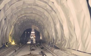
The main component of the waterproofing system described above involves an 80 mil (2.0mm) to 120 mil (3.0mm) polyvinyl chloride (PVC) membrane depending on complexity of the application. The membrane is typically unreinforced, however, where needed because higher structural properties are sought the membrane contains reinforcement by a glass fiber regular grid or a dispersed fiber carrier. While the 80 mil unreinforced membranes are often used in line tunnel applications (Figure 2) PVC sheets of 100 mil thickness are stronger yet provide sufficient flexibility to enable a satisfactory wrap around corners and an adjustment to uneven surfaces and are specified for cut-and-cover waterproofing applications.
One major advantage of the flexible PVC membrane is that sheets which are typically provided in six (6) feet widths and endless rolls are welded together using double weld seams, which are tested for tightness. Thereby a truly continuous membrane is established, a characteristic that typically cannot be provided by many other membrane types. Polyethylene (PE) membranes have been improved in flexibility in recent years and their application is being further considered. Polypropylene membranes have been applied where flamability and toxicity have to meet limits beyond construction duration. Other materials are provided, but serve primarily protective purposes. These include geotextiles, which are attached to the support of excavation walls, rock wool or recycled, type PVC membranes which are fixed to the waterproofing membrane for its protection against punctures, welding spatters, etc. Lean concrete is used to protect the membrane on horizontal surfaces or inclined surfaces.
Planning
Mined tunnels and stations represent line structures or assemblies of line structures. Construction sequencing is a relatively straightforward task. Application of the waterproofing system in mined tunnels is often associated with good surface qualities in terms of evenness and roughness, typically shotcrete or pre-cast concrete. Where needed, and in addition, the surface quality can be enhanced by additional layers of shotcrete, often referred to as shotcrete smoothness layers or patches of mortar. In contrast, cut-and-cover construction of subway stations involves an array of complex geometries of vent shafts and ducts, intersections, escape shafts, escalator ways, buildouts, service rooms, etc. The surfaces to which waterproofing is to be applied to are typically rough and by materials inhomogeneous including soldier pile and lagging walls, either braced or secured by tie-backs. Construction sequences have to incorporate large amounts of reinforcement work, bracing removal, staged concrete pours, etc. All these construction activities and surface characteristics increase the level of risk for damage of the membrane based waterproofing system. This fact had to be acknowledged in the design and installation of the waterproofing system in cut-and-cover structures.
Waterproofing for Cut-and-Cover Structures
In the mid nineties WMATA adopted a PVC geomembrane as the main component for its new waterproofing system for cut-and-cover structures. Prior to its final acceptance however, European case histories where this waterproofing system had been successfully installed were analyzed and the requirements for design and installation established. Case histories included cut-andcover subway stations constructed in Dortmund, and Essen, Germany, and the main library in Zurich, Switzerland (Aeppli, 1992) among many others. From the review of these case histories and from lessons learned in cut-and-cover waterproofing systems at WMATA it became apparent that a further step had to be taken toward the application of this waterproofing system in cut-and-cover construction. The much higher complexity of both structure and construction processes associated with cut-and-cover construction when compared to mined tunnels had to be acknowledged, and two main guidelines for the design of cut-and-cover waterproofing systems were established. First, the waterproofing design has to accommodate increased complexity by being adequately detailed, especially in problem areas. Secondly, an additional safety factor has to be introduced allowing for a built-in procedure for remedial work after construction if a leak had gone undetected during construction. This makes the system much more controlled.
Consequently, the design procedures developed address the following:
Installation sequence:
This relates to installation of-the waterproofing system relative to the construction, in particular in relation to the removal of the bracing and the protection of the membrane during its removal. As part of the design, a set of drawings is developed which depicts the anticipated construction sequencing of support of excavation, final structure and the waterproofing `sandwiched' between.
Design details:
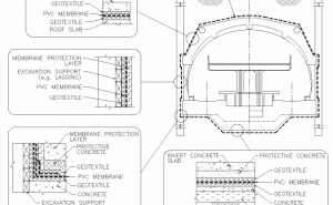
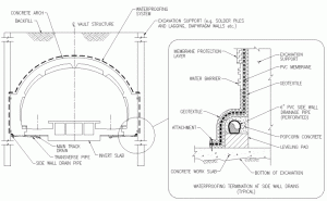
This relates to the need to develop design details for typical waterproofing installation including protective layers, arrangement at corners and transitions, connection details at adjoining tunnels, penetrations, protective measures for membrane prior to and during backfill, and termination details near the surface to name the most relevant ones. It also foresees protective measures during strut removal and other site specific activities that might require special attention as not to damage the waterproofing. Typical sections are shown in Figure 3.
Sectioning:
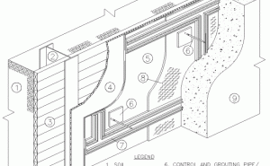
Controlled repair measures are provided for by the so called `sectioning'. Sectioning refers to the concept of subdividing the total waterproofing membrane area into smaller, individual areas referred to as sections by means of base seal waterbarriers. To allow for controlled grouting between membrane and concrete surface, these individual sections are limited to a size of about 80 - 100 m2. In locations of corners and transitions, they may be laid out even much smaller in size. Should water leakage occur it will be limited to the individual section and not migrate uncontrolled around the entire structure following the path of least resistance. Within this section control and grouting pipes are installed at its lowest and highest points. These pipes penetrate through the final structures' walls and are in contact with the membrane (Figure 4). They serve a twofold purpose. Should leakage have occurred within the section, then water will find its path to these pipes and exit there. This way leakage will be detected. In case of leakage, the same pipes are used for injection of special grouts through these pipes. The injection of grout again, as the water migration previously, will only be limited to the leaking section. Once cured, the grout will provide a very low permeability, secondary waterproofing layer.
Rehabilitation of Tunnels and Underground Structures
Efficient waterproofing systems for underground structures were developed in the 1970s. Today clients will insist on the inclusion of such a system at the early design stage of an underground project. There is, however, a large number of tunnels and underground structures that were built without adequate water control systems.
Water leakage into tunnels often jeopardizes the structural integrity of the facility, its mechanical and electrical installations, and may compromise the safety of operations. Past repair practices aimed at preventing leakage by grout injection of linings and the adjacent ground with cement or resin grouts have shown limited success. Therefore, the flexible membrane waterproofing system has been adapted and installed in existing underground structures to control water ingress by drawing it to an effective drainage system. Both waterproofing membrane and drainage system can, if necessary, be insulated against the damaging effects of freezing temperatures. The waterproofing system, protected by panels, shotcrete, cast-in-place concrete or similar, provides for a clean, and easy to maintain interior of the underground space and installation work can be carried out in consideration of the need to maintain operations.
Installation
There are two basic requirements for the installation of this waterproofing system: a skilled installation and a thorough, experienced and, most importantly, dedicated inspection. The specifications call for a minimum installer's experience in the installation of this waterproofing system in underground construction. Furthermore the specifications were established such as to require submission of installation procedure shop drawings. This way modifications made to the construction in the field or other conditions that may not have been anticipated in the design can be addressed jointly during the construction. A detailed quality assurance program has also been incorporated in the specifications that combines checklists and approval procedures.
By far the biggest role that has to be provided by the inspection personnel is to assure that other construction activity such as the installation of rebar cages, the removal of struts, setting up of form work, backfilling and compaction activities do not jeopardize the integrity of the waterproofing system
It is also very important on site to raise awareness of the waterproofing system by these other disciplines, as any measure that must be taken to repair the membrane, even if this only consists of heat welding another PVC patch on top of a puncture, will involve disruption and delay in subsequent works.
CASE HISTORIES
Since the mid-nineties, this waterproofing system was required by WMATA for all cut-and-cover structures of the Mid-City E-Route involving the Georgia Avenue-Petworth and Columbia Heights stations, and a number of emergency access and ventilation shafts and almost all underground portions of the Outer F-Route. A station structure typically consists of service rooms which are arranged to both sides of the about 600-foot long public station area. All these structures use the so called `closed bag' system, meaning that they are completely wrapped into this waterproofing system (Figure 5). The adjoining running tunnels and crossovers use the same waterproofing system, making waterproofing system connections reliable.
In permeable soils as is the case at the Mid-City ERoute a closed system eliminates the continuous pumping of large ground water volumes and restores the natural ground water regime to practically pre-construction levels. Thereby surface settlements often associated with groundwater drawdown are minimized. It also eliminates the need for treatment costs of potentially contaminated ground water that may be present at locations.
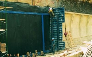
The MBTA in Boston, MA, has also adopted the use of the PVC membrane based waterproofing for their new construction contracts for the South Boston Piers Transitway (Cormani, 1999). Figure 5 shows the `closed bag' waterproofing installation at the box tunnels for MBTA !s South Piers Transitway Section CCO9. Prior to construction of the concrete slab the waterproofing had been installed in the invert. Upon completion of the concrete walls and roof individual membrane sheets are hung at the structure walls and roof by means of welding to PVC attachment disks. The sheets are then welded together to form a continuous membrane layer. The membrane is also welded to the waterbarrier grid which has been attached to the inside of the formwork thereby embedding the waterbarrier ribs and creating the basis for the sectioning system. In contrast to the `closed bag' system the `open system' has been utilized at the Glenmont Station of the Outer B-Route (Figure 6). The Glenmont Station is located just north of the mined tunnels of Section B 11 a which use a similar waterproofing system with side wall drains.
With the invert located in bed rock low water inflow rates are expected through the sidewall drainage system at Glenmont Station. The philosophy behind the open system is different in that it controls the path of water whereas the closed system practically prevents a penetration into the structure. In the open system water is guided through the relatively permeable geotextile which separates the membrane from the support of excavation to the sidewall drain pipes. From here groundwater is collected and conducted into the main track drain and drainage sumps. The advantage of the open system is that it prevents the buildup of high hydrostatic pressures and in case of minor damages in the membrane water will be guided to the drainage system rather than penetrate through the membrane. Figure 7 shows waterproofing installation with adjacent finished lower arch concrete pour at Glenmont Station.
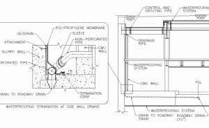
The WMATA cut-and-cover stations and MBTA's World Trade Center Station box tunnels utilized the PVC waterproofing system sandwiched between the support of excavation and structure wall or structure wall and backfill material. At MBTA s Courthouse station a different approach has been taken due to the station construction method selected. In the above described examples the waterproofing layer is situated `outside' the actual structure separated by a concrete wall from the interior. At MBTA's Courthouse station however, the support of excavation wall has been designed to serve as the permanent structural wall for the design life of the project. The public station interior including station platforms, mezzanines and concourse spaces is separated from this permanent slurry wall merely by an architectural CMU block wall (Figure 8).
The space between CMU and slurry wall is accessible for maintenance as needed. The waterproofing system is by its character an `open system', as all water seeping through the slurry walls is collected in a drainage layer between membrane and the slurry wall and guided into an internal system of drainage pipes. This drainage pipe system collects the water seeping in and discharges it to the main track drainage pipe. Where drain pipes are used, provisions for clean-outs have to be made for maintenance to keep the system free of debris and prevent clogging (Figure 8, Detail).
The rehabilitation of the almost forty year old Lehigh Tunnel No. 1 by the Pennsylvania Turnpike Authority became necessary in the mid nineties to eliminate wet road surfaces, calcifications and formation of ice in the air duct. A PVC membrane and thermal insulation were installed in the ventilation air duct over most of the tunnel length. PVC membrane sheets and rock wool insulation boards were placed against the concrete lining of the tunnel in the air duct, which is separated from the vehicular space by a false ceiling. Water diverted by the flexible membrane system is collected by perforated drain pipes at the horizontal membrane termination. The drain pipes are equipped with heating wires to avoid freezing of the collected water. Vertical drain pipes installed as part of the waterproofing system throughout the tunnel divert the collected water to the tunnel main drain. These vertical drains also collect water from relief holes drilled into the rock to create a controlled water seepage into the vertical drains at predetermined locations.
Refurbishing of the Berry Street Tunnel, a 25 ft. wide, double track tunnel in Pittsburgh, PA in the late nineties allowed the installation of a waterproofing system. After the removal of a 26 in. thick brick lining, geotextile and flexible membrane sheets were installed at the reinforced shotcrete initial support. The waterproofing system was designed as Track 4 - Research & Development an 'open system' with side drains, manholes and drain lines from side drains to road drain at manholes. A 12 in. thick unreinforced concrete lining was placed as final structural support and protection for the waterproofing system. A recent visit to the tunnel revealed the success of the waterproofing as the interior space is completely dry.
CONCLUSION
The projects at Washington, DC Metro have shown that waterproofing systems based on the use of flexible membranes can achieve dry underground structures when the three pillars are implemented in the building process; system compatibility, thorough planning and experienced installation and inspection. The owner's assessment as reported in FTA's lessons learned program is a good indication of the system's performance "The new waterproofing system implemented for the construction of the Metrorail Outer B-Route has produced exceptionally dry conditions in both tunnels and underground stations", and "WMATA anticipates that future operating and maintenance costs will be substantially reduced for facilities constructed using. the new waterproofing system. However, rail car air filters will require more frequent replacement due to increased dust levels created by the drier conditions..." Installation costs are similar to other waterproofing methods frequently applied, but the PVC system is controlled, more economic in long-term and provides owner and user with a clean and dry quality end product.
ACKNOWLEDGMENTS
The authors would like to thank project managers of the Outer B-Route, the Mid-City E-Route and Outer F-Route, Messrs. John Yen, Jack Dickson and Jack Donahue respectively for their pursuit of innovation and their support in implementing this waterproofing system at WMATA. Similarly, we would like to thank Messrs. David Ryan and Philip Montoni of the MBTA for their support in applying the system for cut-and-cover and mined tunnels of MBTA's South Boston Piers Transitway in Boston, MA.
ENDNOTES
- Anon., "Lessons Learned No. 31, Topic: Waterproofing and Its Effect on Operations and Maintenance of Underground Facilities", Federal Transit Administration Lessons Learned Program, 1999. http://www.fta.dor.gov/ library/program/lesson.htm
- Sauer, G., Garrett, V X, "Achieving A Dry Tunnel", Rapid Excavation and Tunneling Conference `87, Proceedings, 1987.
- Meggl, A.R, "Tunnel Sealing System Based on Plasticized PVC Sheeting", Kunststoffe im Bau, Heft 4, Hanser, Munich, Germany, 1980.
- Martin, D., "Dry run for Washington Metro gives NATM an American boost", Tunnels & Tunnelling Magazine, May 1987.
- Irshad, M., Dickson, J.RV, "Subway Construction: Options and Issues", American Public Transportation Association 1995, Rapid Transit Conference, New York, NY, June 1995.
- Mergelsberg, W, Gall, V., Sauer, G., "Achieving Dry Cutand-Cover Stations - A Membrane Based Waterproofing System for Underground Structures", North American Tunneling `96, Proceedings, 1996.
- Aeppli, Heini, "Wasserdicht und sicher wie ein Hochseedampfer", Schweizer B aublatt, Nr. 7, 28. Januar, Bautenschutz Nr. 1. 1992.
- Cormani, D.L., "Going underground: Waterproofing on Boston's CA/T project", Geotechnical Fabrics Report, March 1999.
