You are here
Achieving Dry Cut-and-Cover Stations
Proceedings of the International Conference on North American Tunneling 1996 and the 22nd General Assembly of the International Tunneling Association, 21-24 April 1996
1. INTRODUCTION
Based on its success in achieving dry stations and tunnels in mined construction flexible waterproofing membranes are now being utilized for remedial waterproofing of old, leaking tunnels and for the waterproofing of cut-and-cover stations.
In the early 80's the Washington Metropolitan Transit Authority (WMATA) approved a value engineering change proposal for the construction of their Section B10, Wheaton Station. The VECP relied on the use of the NATM (New Austrian Tunneling Method) and by the economic approach of the concept promised cost savings. The selling point finally, however, was the proposed waterproofing system that relied on the use of flexible, plastic membranes. Now more than ten years after construction the Wheaton Station, and running tunnels remain completely dry, creating a comfortable space for Metro's patrons and an untroubled environment for the operations and maintenance staff. Since its success in Washington this waterproofing system has been adopted for many highway tunnels and subway structures.
With the extension of Metro's Redline to the north and completion of its Mid-City E-Route WMATA is again pioneering the field of waterproofing in the US by applying flexible, plastic membranes for the waterproofing of cut-and-cover structures. The Glenmont, Georgia Avenue-Petworth and Columbia Heights stations will utilize this same concept. While the Glenmont station uses the 'open system' with side wall drains, the Mid-City E-Route will rely on the 'closed system' by wrapping the entire structure into the membrane.
The same system is also being utilized for the remedial waterproofing of existing metro and highway tunnels and has recently been successfully applied at the Lehigh Tunnel No.1 in Pennsylvania.
2. WATERPROOFING SYSTEM
When designing a waterproofing system, be it for a new structure or remedial reasons it has to be acknowledged that the structure and its surrounding ground constantly undergo a change over time. A global tide, stress redistributions, temperature and moisture changes, sedimentation, erosion and other factors continuously change the path of water in the geologic host formation surrounding the underground structure. The structure itself exhibits changes in temperature, moisture and internal and external time dependent loadings which cause joints to open and close, creating new cracks, clogging up old ones, etc.
Knowledge of these facts led to the current worldwide acceptance of membrane type waterproofing systems because membranes bridge all of the above-mentioned openings, dislocations and other strain related movements (Sauer, et. al., 1987).
When adopting a membrane based waterproofing system the following minimum requirements must be met:
- The waterproofing system must be continuous.
- The membrane must be able to adapt to irregularities of surfaces it is attached to.
- The membrane must remain permanently impervious despite rheological or structurally caused movements (long term behavior of ground, temperature variation, vibration, or shrinking and creeping of concrete).
- The waterproofing system must be able to bridge small cracks in the construction surface. It must be able to absorb discontinuous stress-variations and to a certain extent provide sufficient tensile strength.
- The waterproofing system must be resistant to aggressive water, wether from natural sources or contaminated ground, and to biological attacks.
- The waterproofing system must be suitable for installation on damp and wet surfaces. It must be easy to handle and to install. Installation must be possible in large quantities with the help of reliable, mechanized methods at acceptable costs.
- The material must be self extinguishing in case of fire.
- It must be possible to check the waterproofing system for potential damage and to easily repair before placement of the concrete elements of the final structure.
- Provisions must be obtained for post construction remedial works.
A waterproofing system that would satisfy these requirements was developed in the early seventies mainly in Switzerland and in Austria, combining a non-woven polypropylen geotextile and a high-polymer sealing membrane. The excellent results, obtained in the course of the construction of several important road tunnels in the Alps, consequently encouraged use of this new waterproofing system in subway and railroad tunnels and even shafts (Meggl, 1980). Soon afterwards the method was adopted, together with the NATM by most European Countries. In the mid eighties this waterproofing technique was first introduced in the U.S. at Section B10, Wheaton Station of the Washington Metropolitan Area Transportation Authority (Martin, 1987). Since then the application of this system that now relies on the geotextile and flexible plastic membrane has become standard in tunnel sealing applications in highway and subway tunnels (Irshad et. al., 1995) in the U.S.
While this membrane waterproofing system continued its successful and increasing application in mined tunnel construction in parallel investigations were made into its use for other underground structures constructed by cut-and-cover and open cut techniques. Soon European cut-and-cover tunnel approaches, underground parking garages, deep basements of sensitive public and commercial purposes and finally cut-and-cover subway tunnels and stations were successfully protected against the ingress of water using this waterproofing system.
The step that had to be taken toward the application in cut-and-cover construction was to acknowledge the much higher complexity of both structure and construction processes when compared to mined tunnels. Mined tunnels and stations represent line structures or assemblies of line structures. Construction sequencing is a relatively straightforward task. Application of the waterproofing system in mined tunnels is to an in general good surface, typically shotcrete or pre-cast concrete. Where needed in addition, the surface preparation can be easily provided. In contrast, cut-and-cover constructions of subway stations involve an array of irregular vent shafts and ducts, escape shafts, escalator ways, build-outs, etc. The application faces typically rough and by materials inhomogeneous soldier pile and lagging walls, either braced or secured by tie-backs. Construction sequences have to incorporate large amounts of reinforcement work, bracing removal, staged concrete pours, etc. All these construction activities and surface characteristics add to vulnerability of the membrane based waterproofing system. This fact had to be acknowledged in the design and installation of the waterproofing system in cut-and-cover structures.
3. WATERPROOFING SYSTEM FOR CUT-AND-COVER STRUCTURES
Similarly to the materials frequently used for the waterproofing of mined tunnels at the Washington, D.C. metro, WMATA adopted a polyvinyl chloride (PVC) geomembrane as the main component for its new waterproofing system. Prior to final acceptance however, European case histories where this waterproofing system had been successfully installed were analyzed and the requirements for design and installation established. Case histories included cut-and-cover subway stations constructed in Dortmund, and Essen, Germany, and the main library in Zurich, Switzerland (Aeppli, 1992) among others.
3.1 Materials
The main component of the waterproofing system involves a 100 mil (2.5mm) unreinforced PVC membrane. The flexibility characteristics of a PVC sheet at 100 mil are sufficient to enable a satisfactory wrap around corners and an adjustment to uneven surfaces. One major advantage of the flexible PVC membrane is that sheets which are typically provided in six (6) feet widths and endless rolls are welded together using double weld seams, which are tested for tightness. Thereby a truly continuous membrane is established, a characteristic that typically cannot be provided by many other membrane types. Also polyethylene (PE) membranes have improved their flexibility in recent years.
Other materials are provided, but serve primarily protective purposes. Geotextiles, which are attached to the support of excavation walls, rock wool or recycled type PVC membranes which are fixed to the 100 mil waterproofing membrane for its protection against punctures, welding spatters, etc. Finally lean concrete at four (4) inch of thickness is used to protect the membrane on horizontal surfaces.
3.2 Design
To account for increased complexity of installation and construction two main guidelines for the design of cut-and-cover waterproofing systems were established. First, the waterproofing design has to accommodate increased complexity by being adequately detailed, especially in problem areas. Secondly, an additional safety factor has to be introduced allowing for a built-in procedure for remedial work after construction should a leak had gone undetected during construction. This makes the system much more controlled.
Consequently, the design procedures developed addresses the following:
Installation sequence:
This relates to installation of the waterproofing system relative to the construction, in particular in relation to the removal of the bracing and the protection of the membrane during removal.
Design details:
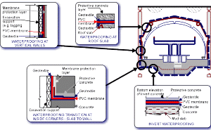
This relates to the need to develop design details for typical waterproofing installation including protective layers, arrangement at corners and transitions, connection details at adjoining tunnels, penetrations, protective measures for membrane prior to and during backfill, and termination details near the surface to name the most relevant ones. It also foresees protective measures during strut removal and other site specific activities that might require spacial attention as not to damage the waterproofing. Typical sections are shown in Figure 1.
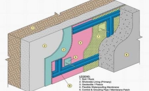
Controlled repair measures are provided for by the so called ‘sectioning' or ‘grid'. Sectioning refers to the concept of subdividing the waterproofing membrane into individual areas (grid) referred to as sections by means of base seal waterbarriers. Should water leakage occur it will be limited to the individual section and not migrate uncontrolled around the entire structure following the path of lest resistance. Within this section control and grouting pipes are installed at its lowest and highest points. These pipes penetrate through the final structures' walls and are in contact with the membrane (Figure 2). They serve a twofold purpose. Should leakage have occurred with the section then water will find its path to these pipes and exit there. This way leakage will be detected. Once detected the same pipes are used for injection of special grouts through these pipes. The injection of grout again, as the water migration previously, will only be limited to the leaking section only. Once cured it will provide a very low permeability and act as the second and remedial waterproofing layer.
This waterproofing system has been foreseen for all cut-and-cover structures of WMATA's Mid-City E-Route and involves the Georgia Avenue-Petworth and Columbia Heights stations, and a number of emergency access and ventilation shafts.
A station structure typically consists of service rooms which are arranged to both sides of the about 600-foot long public station area. All these structures use the so called ‘closed bag' system, meaning that they are completely wrapped into this waterproofing system (Figure 1). The adjoining running tunnels and crossovers use the same waterproofing system, making waterproofing system connections reliable.
In permeable soils as is the case at the Mid-City E-Route a closed system eliminates the continuous pumping of large ground water volumes and restores the natural ground water regime to practically pre-construction levels.
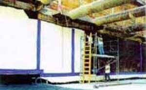
Thereby surface settlements often associated with groundwater drawdown are minimized. It also eliminates the need for clean up costs of potentially contaminated ground water that may be present at locations. Figure 3 shows waterproofing installation at Georgia Avenue-Petworth station in the invert and sidewalls.
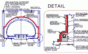
In contrast to the closed system the ‘open system' is utilized at the Glenmont Station of the Outer B-Route (Figure 4). The Glenmont Station is located just north of the mined tunnels of Section B11a which use a similar waterproofing system with side wall drains.
With the invert located in bed rock low water inflow rates are expected through the sidewall drainage system at Glenmont station. The philosophy behind the open system is different in that it controls the path of water whereas the closed system practically just prevents a penetration into the structure. In the open system water is guided through the relatively permeable geotextile which separates the membrane from the support of excavation to the sidewall drain pipes. From here groundwater is collected and conducted into the main track drain and drainage sumps.
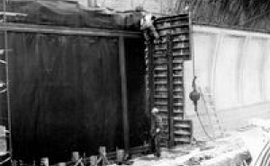
The advantage of the open system is that it prevents the buildup of high hydrostatic pressures and in case of minor damages in the membrane water will be rather guided to the drainage system than to penetrate through the membrane. Figure 5 shows waterproofing installation with adjacent finished lower arch concrete pour at Glenmont Station.
3.4 Installation
There are two basic requirements for the installation of this waterproofing system: a skilled installation and a thorough and experienced inspection. The specifications therefore call for a minimum installer's experience in the installation of this waterproofing system in underground construction. Furthermore the specifications were established such as to require submission of installation procedure shop drawings.
This way modifications made to the construction in the field or other conditions that may not have been anticipated in the design can be addressed jointly during the construction. A detailed quality assurance program has also been incorporated in the specifications that combines checklists and approval procedures. By far the biggest role that has to be provided by the inspection personnel is to assure that other construction activity such as the installation of rebar cages, the removal of struts, setting up of form work, backfilling and compaction activities do not jeopardize the integrity of the waterproofing system. It is furthermore important on site to raise awareness toward the waterproofing by these disciplines, as every measure that must be taken to repair the membrane, even if this may only consist of heat welding another PVC patch on top of a puncture, will involve disruption and delay in subsequent works.
4. REHABILITATION OF TUNNELS
Following successful application of this waterproofing system in mined tunnels and cut-and-cover structures design philosophy and materials were for the first time utilized about 10 years ago to seal off the Felbertauern Tunnel (Sauer, et. al., 1987). This tunnel is located about 5,000 feet above sea level at the Felberntauern Road which connects the southern part of Germany with the industrial area of northern Italy. The tunnel was built using conventional drill-and-blast methods and then lined with cast-in-place concrete.
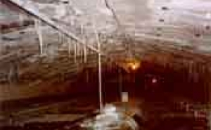
Following its completion in 1968 it was soon plagued by all of the well-known obstacles: wet road surfaces, calcifications, formation of ice, deterioration of the tunnel lining as well as distress to the tunnel users. The tunnel was rehabilitated using the flexible membrane waterproofing system and remains after 10 years virtually dry. A very similar situation was found at the Pennsylvania Turnpike Commission's Lehigh Tunnel No. 1. This tunnel is located at the Turnpike's northeast extension located just several miles north of Allentown, PA and was built in 1957. In addition to the obstacles as outlined above the tunnel maintenance crews were regularly forced during the wintertime to remove icicles which were building up behind the false ceiling of the ventilation air duct (Figure 6). Following completion of the new Lehigh Tunnel No. 2 which runs parallel to the old one the Turnpike was in the position to close the old tunnel for rehabilitation purposes during most parts of the week. Rehabilitation of Lehigh Tunnel No. 1 commenced in late 1994 and has been substantially completed by November 1995.
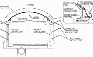
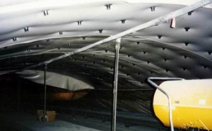
Similarly to the ‘open system' as described earlier the tunnel rehabilitation concept uses a continuous, flexible membrane to collect water and convey it to a drainage system (Figure 7). As shown the waterproofing is applied in the airduct. Water collected by the perforated drain pipes is discharged through diversion holes to vertical drain pipes which are installed as part of the corrective waterproofing measures. These vertical drain pipes also collect water from relief holes which are installed at regular distance throughout the tunnel at vertical drain locations. In the air duct an insulation cladding consisting of a nominal 2-inch thick rockwool board is applied to prevent the water from freezing behind the 60 mil. thick PVC membrane. In addition a heating wire is installed in the longitudinal drain pipes. The wire is connected to an automatic sensor which turns on power once temperatures fall below a preset temperature. Figure 8 displays the air duct during membrane installation.
5. CONCLUSION
Case histories have shown that waterproofing systems based on the use of flexible membranes can achieve dry underground structures. Through enhancement of design level, installation skill, and adequate inspection these techniques are available for cut-and-cover structures and the rehabilitation of leaking tunnels as well. At installation costs similar to those waterproofing methods frequently applied, the introduced system is controlled, more economic in long-term and provides owner and user with a clean and dry quality end product.
ACKNOWLEDGEMENTS
The authors would like to thank Messrs. John Yen and Larry Heflin of the Outer B-Route and Messrs. Jack Dickson and Jim Haggins of the Mid-City E-Route for their continuing support in implementing this waterproofing system.
REFERENCES
- Aeppli, Heini, 1992. Wasserdicht und sicher wie ein Hochseedampfer, Schweizer Baublatt, Nr. 7, 28. Januar, Bautenschutz Nr. 1.
- Gnilsen, R., Rhodes, G.W., July/Aug. 1986. Innovative Use Of Geosynthetics To Construct Watertight Washington, D.C. Subway Tunnels, Geotechnical Fabrics Report, Vol. 4, No. 4, IFAI, St. Paul, MN.
- Heflin, L.H., 1985. WMATA's Use Of The New Austrian Tunneling Method For Lining And Support, Proceedings, Rapid Excavation and Tunneling Conference, Vol. 1, AIME, New York.
- Irshad, M., Dickson, J.R.V, June 1995. Subway Construction: Options and Issues, APTA Rapid Transit Conference, New York, NY.
- Martin, D., May 1987. Dry run for Washington metro gives NATM and American boost, Tunnels & Tunnelling Magazine.
- Meggl, A.F., 1980. Tunnel Sealing System Based on Plasticized PVC Sheeting, Kunststoffe im Bau, Heft 4, Hanser, Munich, Germany.
- Sauer, G., Garrett, V.K., 1987. Achieving A Dry Tunnel, RETC Proceedings.
