You are here
Benchmark for the Future: The largest SEM Soft Ground Tunnels in the United States for the Beacon Hill Station in Seattle
May 14, 2013
Laubbichler, J., Schwind, T. and Urschitz, G.: Benchmark for the Future: The largest SEM Soft Ground Tunnels in the United States for the Beacon Hill Station in Seattle
NAT 2004
Atlanta, GA, 2004/04/20
USA
North American Tunnel Conference, April 17-21, 2004
Please follow this link to view the presentation (pdf)!
ABSTRACT
Sound Transit's Beacon Hill Light Rail Station in Seattle comprises the largest SEM soft ground tunnels in the United States to date and will be constructed in highly variable glacial soils with multiple groundwater horizons. The design is based on SEM principles, experience from previous projects, engineering judgment and numerical analyses, and provides for the flexible application of various predefined support measures (SEM Toolbox items) to cope with variable ground conditions, assure the most economic construction and minimize risks. A Test Shaft Program with the purpose of gaining additional geological in-formation and confirming design assumptions was carried out. Findings in regard to ground behavior and groundwater were implemented in the design. To reduce construction risks, the owner decided to retain the SEM designers to provide SEM supervision and construction support services.
1 INTRODUCTION
1.1 Project Overview
The Beacon Hill Tunnels and Station are part of the 14 mile initial segment of the Sound Transit Central Link Light Rail Line that will establish a high capacity commuter connection from downtown Seattle to Tacoma. The 4,300 foot running tunnel under Beacon Hill will be mined by Earth Pressure Balance Machine (EPB), while the deep mined Station will be constructed using slurry walls and the New Austrian Tunneling Method (NATM), referred to as Sequential Excavation Method (SEM) for this project.
1.2 Beacon Hill Station Arrangement
From the Station Headhouse, a 181 ft deep, 46 ft inner diameter Main Shaft will be constructed that will house four high speed elevators, emergency staircases, ventilation shafts and mechanical and electrical equipment. A 26 ft inner diameter Ancillary Shaft will accommodate another set of emergency staircases and ventilation shafts. From the Main Shaft, the 41 ft wide Concourse Cross Adit will provide passenger and emergency access to the Platform Tunnels. These are 380 ft long by 32 ft wide and were designed to accommodate the platforms, artwork and architectural finishes, and the light rail tracks. Two Cross Adits will connect the Platform Tunnels, and Ventilation Tunnels will provide air flow in normal operation and for emergencies.
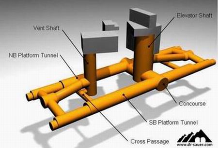
Figure 1: Station Arrangement.
1.3 Design Responsibilities
The Hatch Mott McDonald / Jacobs (HMMJ) Joint Venture is the lead designer for the Beacon Hill Tunnels and Station, the architectural design is carried out by Otak. The Dr. G. Sauer Corporation (DSC) provides the SEM design as a subconsultant for the Concourse Cross Adit, the Platform Tunnels and the Platform Cross Adits; Shafts, Ventilation Tunnels and Running Tunnels are designed by HMMJ.
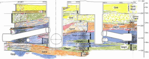
Figure 2: Geologic Profile of Station.
2 GEOLOGY
2.1 Geologic Setting
The Puget Sound Area is characterized by a complex mixture of glacial and nonglacial soils that have been deposited, consolidated, eroded and reworked by multiple major glaciations during the Pleistocene Epoch and numerous seismic events. Beacon Hill is an approximately 300 ft high ridge that is composed of holocene, vashon and prevashon deposits.
An extensive subsurface exploration program has been conducted by Shannon & Wilson, Inc. of Seattle. In the course of this program, more than 70 investigation borings were drilled using Hollow Stem Auger, Mud Rotary, Triple?tube Rotary Core and Sonic Core techniques. Laboratory testing of the recovered soil samples was carried out and engineering properties were derived accordingly.
The exploration program showed that most of the Beacon Hill Station will be excavated within in glacial, overconsolidated, partly fractured or slickensided clays and tills. Intermittent sand and silt layers will be present with multiple perched groundwater horizons.
The Seattle Bremerton Fault zone is expected to be the cause for some of the inconsistencies, inclinations and fractures observed during the geotechnical investigation.
2.2 Ground Classification and Ground Behavior
For design purposes, the soils were grouped into classes according to their engineering parameters and anticipated ground behavior during tunneling:
Class 1: Loose to dense granular deposits
This soil type consists of poorly graded sand and gravelly sand; it will be encountered when excavating the Headhouses and not be of concern for tunneling.
Class 2: Soft to Very Stiff Clay and Silt
This soil type comprises normally consolidated clays, and silty clays and clayey silts; it will be encountered when excavating the Headhouses and not be of concern for tunneling.
Class 3: Till and Till Like Deposits
Heterogeneous mixtures of gravel, sand, and silt or clay; they will be encountered in the station shafts and in sections of the station tunnels.
These soils have a compressive strength similar to very soft rock are expected to stand vertically in an excavation. Water bearing sand and silt lenses may cause local instabilities, unless properly treated.
Class 4: Very Dense Sand and Gravel
This soil type consists of poorly graded sand, gravelly sand and sandy gravel; it will be encountered in pockets and relatively thin layers in the excavation of the station tunnels and will likely be water bearing.
This material has little to no cohesion and will show flowing behavior if charged with water or running behavior if allowed to dry out. Dewatering, pre treatment and special consideration will be required when this material is encountered.
Class 5: Very Dense Silt and Fine Sand
This soil type consists of silty fine sand to sandy silt; it will be encountered over a substantial portion of the Main Shaft excavation and parts of the Concourse Cross Adit.
Under hydrostatic pressure, this material will show flowing behavior. If drained, it is expected to stand well in small to medium sized openings with little face support.
Class 6: Very Stiff to Hard Clay
This soil type consists of overconsolidated silty clay or clayey silt, with some fine sand; it will be encountered in the Main Shaft and most of the station tunnel excavation will be in this material. Slickensided and fractured zones will be encountered during tunnel construction; to take this into account in the design, a further subdivision into Clay A, Clay B and Clay C was considered necessary.
Due to the hard consistency and cohesive nature of this material, it will stand well at excavation faces and will be relatively easy to excavate with a tunnel excavator. In the slickensided and fractured zones, spalling, raveling and wedge failures in the tunnel face and heading may occur if not properly pre supported. Water bearing sand and silt lenses may cause local instabilities, unless properly treated.
The high variability of the geology in the area of the future station poses the main design challenge. Special considerations and flexibility in the design are necessary to address this issue. During construction, a high degree of experience, alertness, and the proper tools to react appropriately to changing ground conditions are needed. Sound Transit therefore decided to extend the services of the design team to provide SEM supervision and construction support services.
In order to get a better understanding of the soil strata and the ground behavior during an SEM type excavation, it was decided to construct an Exploratory Test Shaft and Test Adits within the boundaries of the future Main Shaft. A brief description of the program and the implications for the Station Design are provided in section 5.
3 LARGE SOFT GROUND SEM TUNNELS
3.1 General Considerations
The design philosophy of SEM has been described and documented in depth in numerous publications. The original concept was adapted to be suitable for soft ground tunneling and first used in the Frankfurt Clay in 1968. Since then, means and methods have been developed further and a substantial number of large soft ground tunnels have been constructed in Europe, some of them in adverse ground conditions with shallow overburden. In the United States, soft ground tunnels of the size required for the Beacon Hill Station break new ground.
Some of the key elements for large SEM tunnels in soft ground are:
- Ovoid cross sections with rounded inverts and domed excavation faces to prevent stress concentrations.
- Ring Closure within 1.5 times the tunnel diameter to prevent loosening of the surrounding ground and excess settlements.
- Timely installation of sealing shotcrete / flashcrete and the initial shotcrete lining to prevent deterioration and loosening of the soils.
- Subdivision of the faces into smaller drifts and adjustment of round lengths to be able to control and stabilize the excavation.
- Utilization of the appropriate ground support, face support, presupport and ground improvement measures.
- Monitoring of the structure during construction to assure stability and verify design assumptions.
- The ability to make adjustments in the field to deal with actual ground conditions encountered.
- Experienced Construction Management, Site Supervision and Quality Control to ensure safety and efficiency.
SEM tunnel design has to take these factors into account and relies heavily on engineering judgment and experience from previous projects, but also on advanced Finite Element Modeling Tools to determine the appropriate excavation sequences and support measures.
3.2 Coping with variable Ground Conditions - the 'SEM Toolbox' Approach
When there is some continuity in the geologic strata and ground conditions can be reasonably anticipated for certain reaches, different ground support classes can be predefined. These contain the excavation sequence and the required support measures, i.e. shotcrete thickness, number of spiles, soil nails, etc. However, when highly variable geology is encountered, ground types and ground behavior change within several feet and mixed face conditions are encountered over large portions of the tunnel alignment, a different concept needs to be developed and deployed which is described in the following.
By using the 'SEM Toolbox' approach, a conservative baseline scenario is defined, an excavation sequence is prescribed and standard support measures - e.g. shotcrete, wire mesh and lattice girders - are defined. Depending on the ground conditions encountered, additional support measures ('Toolbox Items') are used on an as needed basis to ensure stability of the tunnel face and the surrounding ground.
These include:
Pre Support Measures
- Rebar Spiling
- Grouted Pipe Spiling
- Metal Sheets
- Grouted Barrel Vault / Pipe Arch
Face Stabilization Measures
- Face Stabilization Wedge
- Pocket Excavation
- Reduction of Round Length
- Face Bolts
Ground Improvement Measures
- Gravity and Vacuum Dewatering
- Permeation Grouting, Fracture Grouting, Jet Grouting
Annular Support
- Additional Shotcrete
- Soil Nails
- Temporary Invert
For estimating purposes, expected location and quantities of Toolbox Items are provided.
This approach provides a high degree of flexibility during construction and makes it possible to control virtually all kinds of ground conditions, thereby greatly reducing the risks of SEM construction. However, it requires that contractors are familiar with the utilization of the mentioned support measures. Experienced site supervision is essential to ensure that the appropriate measures are taken in a timely manner.
The Standard support measures are paid for on a linear foot basis for each tunnel, while the SEM Toolbox items are separate line items and paid for on a unit price basis.
4 DESIGN OF THE BEACON HILL STATION TUNNELS
4.1 Concourse Cross Adit
The cross section of the Concourse Cross Adit, the largest tunnel of the Beacon Hill Station, was developed according to architectural requirements, emergency access / egress considerations, space requirements for mechanical / electrical equipment and the geometry of the junction to the Platform Tunnels.
|
|


4.1.1 Geology
The Concourse Cross Adit will be constructed primarily in Very Stiff to Hard Clay and Till and Till like Deposits, with intermittent, cohesionless pockets of Silt and Fine Sand that may contain pressurized groundwater. Layers of Silt and Fine Sand and Very Dense Sand and Gravel are located at or near the crown of the excavation.
4.1.2 Design
Due to the large size of the opening and the difficult ground conditions especially in the crown, excavation will be carried out using the dual side wall drift method. Grouted with a double packer system under high pressure (1000 psi), the Barrel Vault will provide presupport over the whole length of the tunnel and be used to improve the Very Dense Sand and Gravel.
The maximum specified advance length is 3 ft 4 in., and the maximum separation between the two side wall drifts in longitudinal direction is two rounds.
The stability assessment for the excavation sequence and the inplace structure of the Concourse Cross Adit Tunnels was performed using two three dimensional finite element models and the finite element program ABAQUS. The first model includes the Main Shaft, the breakout from the Main Shaft, the sequential construction of the Concourse Cross Adits and the headwall. The second model is used to assess the breakout from the Concourse Cross Adit into the Platform Tunnels.
|
|


The decision to utilize two models instead of one was made in order to limit model size and therefore keep running times for the finite element code within acceptable limits to facilitate an effective and flexible design process.
The soils in the FE models were modeled using Mohr-Coulomb failure criteria (friction angles from 27º to 40º, cohesion from 0 to 48 kPa), the shotcrete and concrete for the primary and final linings were modeled as linearly elastic materials.
The construction sequence for the Concourse Cross Adit was modeled by completing top heading construction of the side wall drifts, followed by bench and invert. The top heading, bench and invert excavation sequence of the center drift was modeled in the subsequent steps.
As all anticipated construction stages were modeled in the FE analyses, the numerical results were used to assess the stability of the excavation and the excavation face as well as the structural performance of the tunnel linings.
4.1.3 Lining Design
For the section forces determined in the FE analysis, the structural design for the tunnels was performed to meet the requirements of ACI 318.
It could be shown, that a 14 in. thick shotcrete lining (fcu=5000 psi) is capable of providing the required support for the tunnel structure. Due to stress concentrations around the openings in the Concourse Cross Adit at the junction with the Platform tunnels, a local thickening of the primary lining of 17in., was required to avoid additional bar reinforcement.
The final lining is designed for the assumption that the primary lining loses 90% of its stiffness in the course of time. Additionally, the full hydrostatic load is assumed to act on the final lining of the tunnel structures. It could be shown that a 14 in. steel fiber reinforced concrete lining (fcu=5000 psi, fiber content 70lbs/yd3) is sufficient to withstand all the occurring loads. Additional reinforcement is only provided in the junction areas and the connection areas to the headwalls.
4.2 Platform Tunnels
The cross section geometry for the Platform Tunnels was developed according to architectural requirements and train clearance. An additional requirement is the possibility of walking the TBM through the Platform Tunnel for the completion of the east section of the running tunnels.

Figure 7: Platform Tunnel.
4.2.1 Geology
The Platform Tunnels will be constructed primarily in Very Stiff to Hard Clay and Till and Till like Deposits, with intermittent, cohesionless pockets of Silt and Fine sand that may contain pressurized groundwater. Layers of Silt and Fine Sand and Very Dense Sand and Gravel are expected to be located at or near the crown of the excavation in one section of the tunnel, and dry sand ('hour glass sand') can be expected in the invert of the Platform Tunnels in one area of the excavation.
4.2.2 Design
As the tunnel cross section for the Platform Tunnels is somewhat smaller than the Concourse Cross Adit, it was assessed that those tunnels can be constructed utilizing the single side wall drift method.

Figure 8: Single Side Wall Drift.
The stability assessment for the specified construction sequence and the primary and final shotcrete and concrete structure was performed using the second three dimensional FE model.
The Side Wall Drift for the Platform Tunnels is constructed using a top heading bench and invert excavation sequence; the remainder of the tunnel is excavated in the same fashion following the completed side wall drift with a minimum distance of 30'. As all anticipated construction stages are modeled in the FE analyses, the analytical results were used to assess the stability of the excavation and the excavation face as well as the structural performance of the tunnel linings.
4.2.3 Lining Design
For the section forces determined in the FE analysis, the structural design for the tunnels was performed to meet the requirements of ACI 318.
It could be shown, that a 14 in. thick shotcrete lining (fcu=5000 psi) is capable of providing the required initial support for the tunnel structure. As stress concentrations in the ground in the vicinity of the Concourse Cross Adit Tunnels could be observed, a localized thickening of the initial shotcrete lining was required in the junction area.
The final lining is designed for the assumption that the primary lining loses 90% of its stiffness in the course of time. Additionally, the full hydrostatic load is assumed to act on the final lining of the tunnel structures. It could be shown that a 12in. steel fiber reinforced concrete lining (fcu=5000 psi, fiber content 70lbs/yd3) is sufficient to withstand all the occurring loads. Additional reinforcement is only provided in the junction areas and the headwalls.
4.3 Excavation and Support Design and Utilization of NATM / SEM Toolbox
For the construction of each of the SEM tunnels, prescriptive excavation sequences were developed. These contain breakout sequences, advance lengths, sizes of openings, distances to ring closure and distances between side wall drifts. In conjunction with the excavation, the standard support measures, i.e. flashcrete, wire mesh, lattice girders and shotcrete are defined. It is specified that the standard support elements for any round have to be complete prior to commencing the next excavation round in the sequence.
To reduce the uncertainty about ground conditions ahead of the face, the systematic drilling of 35 ft long horizontal exploratory probe drill holes every 6 excavation rounds is specified. The results of the exploratory drilling and the assessment of ground conditions at the tunnel face will be used in the field to determine if there is a need for ground improvement or additional support measures. If so, the appropriate SEM Toolbox Items for the conditions encountered can be utilized to ensure the safety of the tunneling operation. To assist the contractor in choosing the appropriate support measure, requirements for the application of a particular item were defined in the GBR and the Special Provisions.
For the preparation of the bid documents, baseline quantities for each Toolbox Item were defined according to the anticipated geologic conditions.
5 MONITORING
During SEM Tunneling, monitoring, recording and interpreting deformations and stresses of the initial lining is essential to ensure construction safety and to verify the results of the design assumptions.
For monitoring during construction of the mined Station, a comprehensive instrumentation scheme has been developed. Convergence Bolt Arrays will be used to monitor absolute and relative deformations. Concrete pressure cells will record the normal stresses in the tunnel lining, while earth pressure cells will be used to record the ground loads that are transferred to the tunnel lining.
In addition, a surface monitoring program will utilize surface settlement points, inclinometers and extensometers to provide complete information about ground movements during the excavation.
6 WATERPROOFING
The Beacon Hill Station is designed as a "tanked" structure, meaning it will be equipped with a waterproofing system to make it completely watertight. In addition, a Sectioning System is foreseen that will provide remedial repair options in case of leaks. The waterproofing system is installed between the initial shotcrete lining and the final lining and consists of the following elements:
-
Geotextile
A non woven polypropylene geotextile is fastened to the initial shotcrete lining with PVC disks. It is designed to protect the waterproofing layer from sharp projections of the initial lining surface. -
Waterproofing Membrane
The waterproofing layer is the actual sealing element of the system, designed to keep groundwater from the interior of the tunnel. It consists of flexible membrane sheets welded together to form a continuous, impervious layer. This geomembrane is made of a polymeric material, like polyvinylchloride (PVC). Its material properties allow it to adapt to the irregularities of the initial tunnel lining and it is designed to permanently withstand biological and chemical deterioration due to aggressive groundwater. Furthermore, it is fire retardant to minimize safety hazards during construction and operation. -
Sectioning System
The waterproofing system is divided into sections by the means of water barriers. Should a leak occur at a certain location, only one relatively small section is affected, which can be repaired by grouting through preinstalled grout pipes.
7 BEACON HILL TEST SHAFT
7.1 Test Shaft Purpose and Design
In the course of the design process, the designers entertained the idea of a Test Shaft, its purpose being a more thorough understanding of the complex geology and the evaluation of the performance of the SEM construction method. The engineering team designed a 148 ft deep, 18 ft diameter SEM shaft and two Test Adits in different geologic strata within the foot print of the future Beacon Hill Station Main Shaft. By means of the Test Shaft and Adits, ground behavior of the various geologic strata, especially of the water bearing sands/silts considered most critical for tunneling, and of the hard clays, where most of the tunneling work will be performed, should be closely monitored and assessed.
The value of a Test Shaft was determined to be the additional knowledge about geology and ground behavior and the resulting design optimization. Following an assessment of the experiences during construction and the results of the monitoring program, the original assumptions and the resulting design were to be confirmed or modified as required.
7.2 Test Shaft Construction
The construction of the test shaft took place between April 2003 and September 2003.
Deviating from the original intent to construct a shaft using the sequential excavation method (SEM), the contractor decided to excavate the first approximately 50 ft using an auger drill and subsequently install a reinforced shotcrete lining. Once ground conditions worsened and the excavation method using an auger drill could not be further utilized, SEM using a mechanized excavator and a reinforced shotcrete lining was used as prescribed in the Test Shaft design for the following approximately 60 ft.
However, schedule delays and cost overruns, mainly due to more complex ground conditions and additionally employed dewatering measures necessitated the decision to terminate the construction of the Test Shaft before excavating the Test Adits. The test shaft was completed to its intended depth using a 6 ft diameter steel cased boring.
7.3 Test Shaft Findings
Generally, the encountered ground conditions were well suited for SEM construction. For most of the depth the ground remained stable for the full depth of each excavation round (up to 6 ft) and for a considerable length of time (up to 5 hours and more). However, as permeable geologic layers (sands and silty sands) that had not been adequately dewatered, either by means of deep wells or vacuum well points, were encountered, the sides of the shaft excavations locally displayed instability and the contractor could not install the required presupport and support measures in the required time frame.
During the Test Shaft excavation, it could be observed, that the geologic conditions in the Beacon Hill Test Shaft area were more diverse and variable than originally anticipated.
Furthermore, it became apparent that for conditions where groundwater control is critical for the success of the construction method, the usual approach of a contractor designed dewatering system is problematic and should be replaced with an owner designed dewatering system.
It has to be emphasized that the employment of a contractor capable of utilizing SEM principles and SEM Toolbox items in the required manner and time is paramount for the successful implementation of SEM design.
Following the findings of the Test Shaft excavation, risk considerations lead to several design changes as outlined below. The value Test Shaft program was confirmed, as the design changes prior to the bid phase will avoid claims based on inaccurate design assumptions and save more than the costs incurred.
8 REDESIGN
As the findings from the Test Shaft created concern among the designers of the shafts regarding the appropriateness of the SEM excavation in this geology, it was decided to redesign the SEM shafts and replace them with slurry wall shafts.
For the construction of the tunnels, the SEM approach was maintained. The numerical analysis of the Concourse Cross Adit had to be rerun to take the changed geometry and stress regime of the slurry wall into account and the reinforcement and lining thicknesses were adjusted accordingly; the breakout sequences from the shafts were redesigned. Schemes for dewatering from the surface and from within the tunnels were added to the design package. In addition, more stringent requirements for exploratory probe drilling during construction were established and the application of SEM support elements was shown in more detail. Jet Grouting from the surface for the Ventilation Tunnels and to a limited extent for the Platform Tunnels was added. Finally, the anticipated ground conditions were adjusted in the GBR and new baseline quantities and distributions for the SEM Toolbox items were established.
9 CONCLUSION
The challenges posed by the geology and the station arrangement were systematically analyzed and addressed in the production of the design package. Concourse and Platform Tunnels, with widths of 45 ft and 34 ft respectively required the development of sequences able to cope with soft and potentially running conditions, but also very stiff and heavily slickensided soils. The Test Shaft program greatly reduced the uncertainty about the ground conditions and gave the design team the opportunity to evaluate and adjust the design approach. This will pay off as the information gained and implemented in the design package will give the contractors a better basis to bid the project. The decision to extend the designer's services into the construction phase and to task him with the supervision of the SEM works will greatly minimize the construction risks and assure that the design intent is conveyed through construction.
The design and subsequently the construction of the large Beacon Hill Station tunnels will serve as a Benchmark for the future of soft ground SEM tunneling in the United States.
REFERENCES
Duddek, H. and Städing, A. 1990. Tunneling in Soft Ground and Sedimentary Rock for High Speed Double Track Railway Lines in Germany, Tunnelling and Underground Space Technology, Vol. 5, No. 3, pp257-263
Maidl, B. 1995 Handbuch des Tunnel und Stollenbaus. Essen
Pacher, F. and Sauer, G. 1989. Grosse Querschnitte in nicht standfestem Gebirge. Wien: Springer Verlag
Sauer, G. 2003. Ground Support and its Toolbox, ASCE Conference May 6 & 7, 2003. New York City
Shannon & Wilson 2002. Geotechnical Data Report. Seattle
Tunnels & Tunneling International Dec. 2002. Test Shaft to start at Beacon Hill Station: 51
Hatch Mott McDonald Jacobs 2003. Design Report, Seattle
Hatch Mott McDonald Jacobs 2003. Geotechnical Baseline Report. Seattle
Hatch Mott McDonald Jacobs 2003. Test Shaft Report. Seattle
World Tunneling Oct. 2003. Beacon Hill Tunnel Project and Test Shaft: 314-315
Click here to see the full document (application/pdf, 530 KB).