Main Menu

You are here

Soft ground

Chambers Creek Tunnel Access Shafts

Service Performed
Consulting and site supervision for shotcrete lining installation
Commencement - Services
July 30, 2000
Completion - Services
December 30, 2001
Location
Tacoma, WA
United States
Technical data

3 shafts, 12 ft (3.7 m) ID, 40 ft (12 m) to 130 ft (40 m) deep with a sprayed concrete (fcu 25 N/mm²) shell, 6 inches (150 mm) thick. Breakout into a combined sewer line at the bottom of the shaft.

Geology description

Sand / Gravel Clay, galical deposits. Water table at 110 ft (33.5 m) below ground level.

Geology types
Soft ground
Categories
Final cost
$1,500,000
Surface around Shaft Head
Shaft at Surface
View from Base of Shaft

London Bridge Jubilee Line Extension

Service Performed
Detailed temporary and permanent lining design, settlement assessment and construction supervision.
Commencement - Services
November 01, 1994
Completion - Services
June 29, 1997
Location
21 Duke Street Hill
London
United Kingdom
SE1 2SW
United Kingdom
Technical data

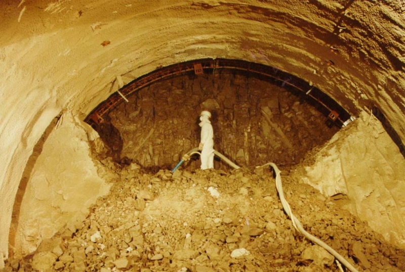
Temporary shotcrete lining design of running tunnels, step plate junction, temporary works access tunnels, shafts, platform and concourse tunnels and ventilation tunnels. Permanent lining design, reinforced concrete and steel fibre reinforced shotcrete.

Geology description

Made ground, alluvium / terrace gravels, London Clay, Woolwich & Reading Beds.
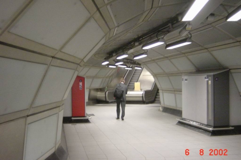
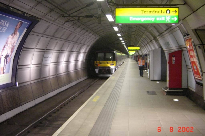
Geology types
Soft ground
Description

London Bridge is a major new station on the 16km long Jubilee extension of London Underground. The vicinity of construction is considered highly sensitive due to old existing tunnels and surface structures. The original design called for hand mining, shield machines for excavation and a segmental cast iron lining for tunnel support. NATM handled the geometrically complicated tunnel alignments and shapes with significantly lower effort. It minimised settlements, which reduced the amount of compensation grouting estimated.

Activity
Final cost
$120,000,000
Complex underground station arrangement
Excavation of tunnel junction
Cross Sections
Geology
Bottom of the Access Shaft
Step Plate Junction
Construction of Intersection
Finished Reinforced Concrete Lining
Project number
183E
Final cost
£120 million GBP

North Shore Connector

Service Performed
Alternative NATM tunnel design, cost estimate & finite element analysis.
Commencement - Services
July 01, 2002
Completion - Services
January 01, 2008
Location
Alpha Dr, Harmar Township
Pittsburgh, PA 15238
United States
Technical data

NATM running tunnel connecting Convention Center station with surface to be constructed beneath historic downtown structures as part of existing LRT system expansion. Provided initial design package, including detailed cost estimate. Tunnel Length: ~446'* Cross Section: 41'-4" x 26'-11"; 895.24 ft^3 *Including widening zone for track cross-over.

Geology description

Fill, alluvium (granular and cohesive), fluvioglacial deposits and bedrock.

Geology types
Soft ground
Description

The North Shore Connector Project consisted of three underground station structures and running tunnels, excavated with TBM and Cut-and-Cover tunneling methods. It also included a twin bore tunnel under the Allegheny River. Dr. Sauer and Partners provided design review and design support services. The development of the waterproofing system for underground structures including tying into an existing station using a flexible membrane system, combined with a sectioning system that allows for section grouting instead of the entire structure if a leak is detected was also provided.

Activity
Final cost
$7,600,000
Construction methods
Project overview
Cut-and-Cover method
Project number
361D
Final cost
$7.6 million USD

Brighton Storm Water Relief Scheme

Service Performed
NATM design of the shaft bottom, TBM chamber, mucking bunker and backshunt
Commencement - Services
June 27, 1993
Completion - Services
November 27, 1993
Location
Brighton
United Kingdom
Technical data

11.6 m diameter shaft, approx. 45 m deep. Concrete segmental construction to 24.95 m OD. NATM construction to the base at -43.25 m OD with a 7.5 m span TBM launch chamber and mucking bunker, 40 m long, and 4.0 m diameter backshunt adit, 13.5 m long.

Geology description

Made Ground overlying Marine Gravels overlying upper Chalk. The NATM shaft and adits were excavated within the Upper Chalk which had numerous flint bands. Seawater was consistently flowing trough the joints and flint bands.

Geology types
Soft ground
Categories
Final cost
$500,000
Longitudinal Section and Cross Section
TBM in Launch Shaft

Rupertustunnel

Service Performed
Geological/geotechnical consultant; preliminary, tender and detailed design; construction support and geotechnical instrumentation monitoring
Commencement - Services
August 21, 1989
Completion - Services
December 30, 1992
Location
Bischofshofen, Salzburg
Austria
Technical data

Railway tunnel twin track, L = 320 m, Cross Section = 110 m², Excavation Sequence: Top Heading, Bench, Invert.

Geology description

Quaternary gravel, sand and silt.

Geology types
Soft ground
Categories
Final cost
$7,800,000
Shotcreting of canopy
Finished portal
Shotcreting of bench
Typical Tunnel Cross Section
Shotcrete Application at Bench
Shotcreting the Canopy Structure
South Portal during Construction
Steel Shutter Assembly
Completed Tunnel at South Portal

JFK International Airport - Access Tunnel

Service Performed
Alternative design study
Commencement - Services
October 21, 2001
Completion - Services
October 21, 2001
Location
New York, NY
United States
Technical data

Two twin tunnels, rail and highway, with a total length of 2,000 ft (610 m) each.

Geology description

Hydraulically filled sand, organic silt, clay and peat, glacial sand, non-compacted fines and occasional gravel.

Geology types
Soft ground
Description

Design study on feasibility of construction of tunnels beneath active airport taxiway using systematic dewatering wells and Door Frame Slab Method.

Categories
Final cost
$42,000,000
Special Construction techniques
Proposed Construction Sequence
Cross Section and Excavation Steps

Heathrow Express Rail Link

Service Performed
Tender design, detailed design and construction supervision.
Commencement - Services
April 01, 1990
Completion - Services
December 27, 1992
Location
Nelson Road
London
TW6 2GW
United Kingdom
Technical data

Railway link between Heathrow Airport and Paddington Station 2 underground stations: (Central Terminal and Terminal 4). Trial station tunnel with three different excavation and support sequences; lenght: 100 m, diameter: 8 m approx.

Geology description

Soft ground, terrace gravels overlying London Clay.

Geology types
Soft ground
Description

The Heathrow Express Link provides a 15 minute high speed rail service between Paddington Station and Heathrow Airport. A 7.25 km spur running for the most part in tunnel provides the airport with underground stations at the Central Terminal area (Terminals 1, 2 & 3) and Terminal 4. Provision was also made for a link to the at this point proposed Terminal 5. The 5.5 km long tunnelled section will pass under the M4 motorway with the portal located to the north.

Activity
Final cost
$2,200,000
Removal of temporary side wall
Shotcrete lining completed
Finished adit
Subway entry at surface
Lattice girder and wire mesh installed at invert
Excavation of bench completed
Excavation of the side drift
Invert,installed lattice girder and wire mesh
Installed pressure cells
Installation of L.G. in top heading of side drift
Proposed Excavation Sequences
Instrumentation Scheme
Finite-Element Calculation
Excavation Sequence Type 1
Excavation Sequence Type 2
Excavation Sequence Type 3
Completed Trial Tunnel
Finished Platform Heathrow Central Terminal
Concourse Tunnel
Completed Escalator Shaft
Project number
172D
Final cost
£2.2 million GBP

Pages