Main Menu

You are here

Soft ground

Hampton Water Treatment Works - C079 Hampton Ozonation

Service Performed
Design and Detailing of Shaft, Base and Breakouts
Commencement - Services
December 31, 1996
Completion - Services
December 31, 1997
Location
Hampton
Middlesex
United Kingdom
Technical data

10.3 m ID shaft, 33.5 m deep with a sprayed concrete (fcu 25 N/mm²), shell 250 mm thick. Two breakout eyes at base level, with 3.73 m diameter 400 mm thick collars.

Geology description

Made Ground, Sand/Gravel Clay (London Clay) Water table at 1.26 m below ground level.

Geology types
Soft ground
Categories

Channel Tunnel Rail Link, Contract 330: Galley Hill Tunnels

Service Performed
Preliminary Design of NATM Alternatives for road under crossing and Barrel Vault Tunnel Alternative for Railway Line under crossing.
Commencement - Services
June 29, 1997
Completion - Services
October 21, 2003
Location
Kent
United Kingdom
Technical data

3 x twin track railway tunnels. Approximately 12m span. Oblique to 35m wide chalk spine. 1 x 7m span access tunnel, 35m long.

Geology description

Weak Rock Upper Chalk and Chalk/Clay fill embankment.

Geology types
Soft ground
Special Construction techniques

Channel Tunnel Rail Link, Contract 330: Pepper Hill Tunnel

Service Performed
Detailed Temporary and Permanent Lining Design, Settlement Assessment and Construction Supervision.
Commencement - Services
December 31, 1996
Completion - Services
December 30, 1997
Location
Kent
United Kingdom
Technical data

Approximately 14 m span twin track railway tunnel. Approximately 200m long. Using doorframe slab method.

Geology description

Superficial soil deposits, highly weathered Chalk and intact weak rock Chalk.

Geology types
Soft ground
Description

Rapid excavation of shallow cut (2m) for slab placement. Safe tunneling beneath operational highway. Minimal disruption to traffic

Taguatinga Tunnel

Service Performed
Doorframe Slab Design Review and Construction Advice
Commencement - Services
December 30, 1997
Completion - Services
December 29, 1999
Location
Brasilia -
Brazil
Technical data

Metro tunnel, 3,950 ft (1200 m) long with a section of approx. 660 sqft (62 m²). Overburden varied from 10 - 15 ft (3 - 5 m), reinforced concrete slab 2 - 4 ft thick.

Geology description

Porous clay, sandy clay, weathered slate, weathered siltstone.

Geology types
Soft ground
Final cost
$20,000,000
Special Construction techniques
Surface Excavation
Installation of Supporting Piles
Start of Slab Construction
DFS - reinforcement, concrete slab partly completed
Clean Surface for Slab Reinforcement
Excavation for the DFS completed, I-beams installed, vaccum system
Installation of Slab Reinforcement
Reinforcement of DFS
Backfill of DFS

Courthouse Station - South Boston Piers Transitway

Client
Service Performed
Waterproofing Design and Supervision
Estimated cost
$1,800,000
Commencement - Services
December 30, 1997
Completion - Services
December 22, 1998
Location
Boston, MA
United States
Technical data

PVC membrane waterproofing at roof and invert for 460 ft (140 m) of Cut & Cover station with additional polypropylene membrance waterproofing and drainage system at side walls. West of the station 975 ft (297 m) of Cut & Cover tunnel with fully applied PVC membrane waterproofing.

Geology description

Sand and gravel overlaying a moderately plastic, organic silt, which exists to a depth of 24 ft (7 m). Below this, layers of uniform fine brown silty sand and sandy silt to 37 ft (11.2 m). Below this stiff olive grey silty clay. High water table.

Geology types
Soft ground
Categories

Metro de Santiago, Linea 2 South Extension, Lo Ovalle to La Cisterna

Owner
Service Performed
NATM design support services and on-site monitoring.
Commencement - Services
January 30, 2001
Completion - Services
December 30, 2004
Location
Av. Libertador Bernardo O'Higgins 1414
Santiago
Chile
Technical data

2.5 km Dual Track Running Tunnels and two Stations with a maximum span of 16.2 m. Excavation of 60-65 m² running tunnel in combined top heading/bench with a subsequent invert excavation. Reinforcement consists of lattice griders and welded wire fabric for initial lining and welded wire fabric for final shotcrete lining.

Geology description

Ripio de Santiago (quaternary conglomerate) consists of a stable matrix of smooth rounded rocks held by bonding fines. Due to earthquake activity it gained compaction and interlocking.

Geology types
Soft ground
Description

The Santiago Metro network comprises five lines. The Linea 2 South extension included 2.5km dual track running tunnels and two stations with a maximum span of 16.2m. Further, an excavation of 60-65m2 running tunnel in combined top heading/bench with a subsequent invert excavation. Reinforcement consisted of lattice girders, welded wire fabric for initial lining and welded wire fabric for final shotcrete lining. Dr. Sauer and Partners assisted in the production of design criteria for the final design and produced finite element structural computations for the large station caverns.

Activity
Final cost
$29,600,000
Construction methods
Excavations of topheading
Shaft and portal
Side drifts, Junction station running tunnel
First side drift
Installation of lattice girder and wire mesh
Headwall
Start-up of sidewall drift
Kurt Egger
Reinforcement of headwall
Compact sand and gravel
Support beam
El Parron South
El Parron South
Sidewall drift
Face support earth wedge located in the top heading
Stress meter
Stress meter
Gerstgrasser Otto
Gerstgrasser Otto
Brunner W.
Dr.Sauer & Gerstgrasser Otto
FEM-Model of Access Tunnel - Station Tunnel Junction
Sidewall Drift Portal
Shotcrete Application
Breakout from Tunnel
Excavation of Center Drift
Demolition of Temporary Sidewall
Mucking out through Access Shaft
Linea 5 - Junction Station-Tunnel
Installation of Tracks
Completion of Electrical Installations in Station
Linea 5 - Finished Station
Excavation of invert
Project number
296E
Final cost
$29.6 million USD

Cameron Run Tunnel

Service Performed
Design, project management and site supervision
Commencement - Services
April 29, 1999
Completion - Services
December 30, 2001
Location
Alexandria, VA
United States
Technical data

Seven 20 ft (6 m) diameter x 200 ft (61 m) long storm water relief tunnels, running through railroad embankment with active train traffic. Removed worst deformations in original steel plate linings with hydraulic expander, re-lined tunnels with steel beams and sprayed 6 inch (150 mm) shotcrete lining.

Geology description

Railway embankment fill consisting of silt with sand, clayey sand and silty sand.

Geology types
Soft ground
Final cost
$3,800,000
Promoseq. 1 of 6
Promoseq. 2 of 6
Promoseq. 3 of 6
Promoseq. 4 of 6
Promoseq. 5 of 6
Promoseq. 6 of 6
Slide 1 of 25
Slide 2 of 25
Slide 3 of 25
Slide 4 of 25
Slide 5 of 25
Slide 6 of 25
Slide 7 of 25
Slide 8 of 25
Slide 9 of 25
Slide 10 of 25
Slide 11 of 25
Slide 12 of 25
Slide 13 of 25
Slide 14 of 25
Slide 15 of 25
Slide 16 of 25
Slide 17 of 25
Slide 18 of 25
Slide 19 of 25
Slide 20 of 25
Slide 21 of 25
Slide 22 of 25
Slide 23 of 25
Slide 24 of 25
Slide 25 of 25
Gerstgrasser Otto
Finished Tunnel Portal
Lining Expander
Invert of Completed Tunnel
Installed Steel Sets
Kurts test Baustellenschild
Expander Arm
Shotcreting of Final lining
Expander on the wheel loader
Expander
Steel Sets
Tunnel Portal after Rehabilitation
SMP, Surface Monitoring Point
SSMP, Shallow Subsurface Monitoring Point
Expander and installed steel sets
Rehabilitated tunnels
Upstream View of Tunnels prior to Rehabilitation
Tunnel prior to Rehabilitation with Timber Support
Trapped Debris due to Bracing
Temporary Dam during Construction to divert Flow
Lining Plate Expander
Lining Plate Expander moving Liner Plates back into Position
200 Tons Hydraulic Jack pushing Steel Lining Plate
Smooth Shotcrete Lining to provide better hydraulic Conditions
Monitoring Data
Upstream View of completed Tunnel Rehabilitation

Beacon Hill Station

Service Performed
NATM / SEM station design and construction supervision.
Estimated cost
$250,000,000
Commencement - Services
February 26, 2000
Completion - Services
December 28, 2007
Location
401 S. Jackson Street
Seattle, WA 98104
United States
Technical data

NATM Light Rail Station located 150 ft (46 m) beneath surface. Station complex includes central elevator/access shaft, concourse, opposing platform tunnels and cross passages. Platform Tunnel Section: 36 ft w x 31 ft h; Platform Tunnel Area: 925 sqft (86 m²); total Station Excavation Area: 63,000 sqft (5853 m²).

Geology description

Over-consolidated glacial clay and till with fracutured zones. Intermittent sand and silt layers with perched groundwater.

Geology types
Soft ground
Description

The Beacon Hill Tunnels and Station are part of the 22.5km initial segment of the Sound Transit Central Link Light Rail Line that will establish a high capacity commuter connection from downtown Seattle to Tacoma. The 1300m running tunnel under Beacon Hill will be mined by Earth Pressure Balance Machine (EPB), while the deep mined Station will be constructed using slurry walls and the New Austrian Tunneling Method (NATM), referred to as Sequential Excavation Method (SEM) for this project.

Activity
Bid cost
$280,000,000
Final cost
$280,000,000
Construction methods
Tunneling under
Max Overburden
Min:120 Max:140
Beacon Hill Station layout
Tunnel excavation under way
3D rendering of Beacon Hill Station complex
Platform tunnel cross section
Schwind Thomas
Installation of Vacuum Dewatering
Rendering of Beacon Hill Station
Project number
325
Final cost
$280 million USD

Channel Tunnel Rail Link - Corsica Street Ventilation Shaft and Tunnels

Service Performed
Design services and technical support during construction.
Commencement - Services
August 27, 2001
Completion - Services
May 27, 2002
Location
73 Collier St
London
N1 9BE
United Kingdom
Technical data

Main Shaft: 18 m (59 ft) dia., depth 30 m (98 ft); Inspection Shaft: 11m (36 ft) x 7 m (23 ft) elliptical, depth 10 m ; Ventilation tunnel: width: 6 m(20 ft) x height: 12 m (39 ft) elliptical.

Geology description

London clay with sand lenses.

Geology types
Soft ground
Description

The Corsica Street Ventilation Shaft comprises the permanent pressure relief and ventilation adit connecting the down line running tunnel to the shaft and temporary access adit tunnel. The ventilation adit was designed as a permanent sprayed concrete lined tunnel built in two phases: primary and secondary linings. The required watertightness was reached by staggering the joint locations between primary and secondary linings, utilising internal curing agents and steel fibres in the secondary lining sprayed concrete and injecting flexible tubes into joints of the secondary lining.

Activity
Categories
Final cost
$110,000,000
Construction site
Breakout from shaft
3D Model of tunnels and shaft
Shaft Base
Excavation of Service Tunnel
Exacvation of Cross Adit
Bench and Invert Excavation
Formwork for Final Lining
Excavation steps
Lattice Girder, Wire Mesh and Shotcrete Detail
Excavation and support steps
Shotcreting of 2nd layer
Lattice Girder installation
Lattice girder, wire mesh and shotcrete
Block-out in shaft lining for tunneling
Excavation for the collar
Reinforcement for the shotcrete collar
Shotcreting of the collar
Project number
340E
Final cost
£110 million GBP

Channel Tunnel Rail Link - Wayside Ventilation Shaft and Tunnels

Client
Service Performed
NATM alternative design and site supervision.
Commencement - Services
February 25, 2002
Completion - Services
October 20, 2003
Location
1 Kemble St
London
WC2B 4AN
United Kingdom
Technical data

2 ventilation tunnels: 32 m² (344 sqft), 2 enlarged ventilation tunnels: 38 m² (409 sqft), 2 drop shafts: 75 m² (807 sqft), 1 horizontal and inclined emergency intervention tunnel: 19 m² (205 sqft), 1 horizontal cross passage chamber: 31 m² (334 sqft) with 4 cross adits underlining the London - Tilbury railway lines.

Geology description

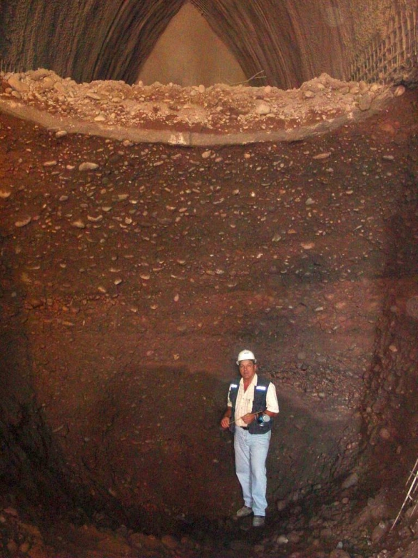
Made ground, terrace gravel, London Clay formation; groundwater level 1m bgl; cover to terrace gravel less than 3m.
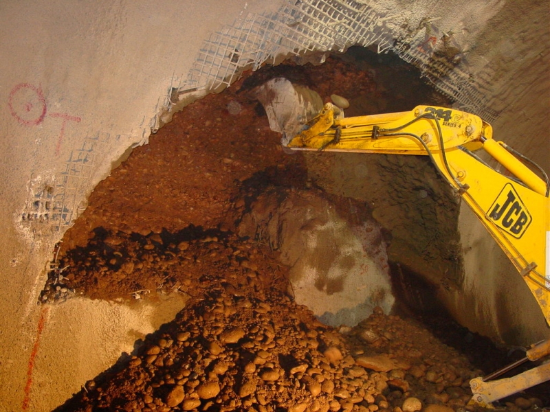
Geology types
Soft ground
Description

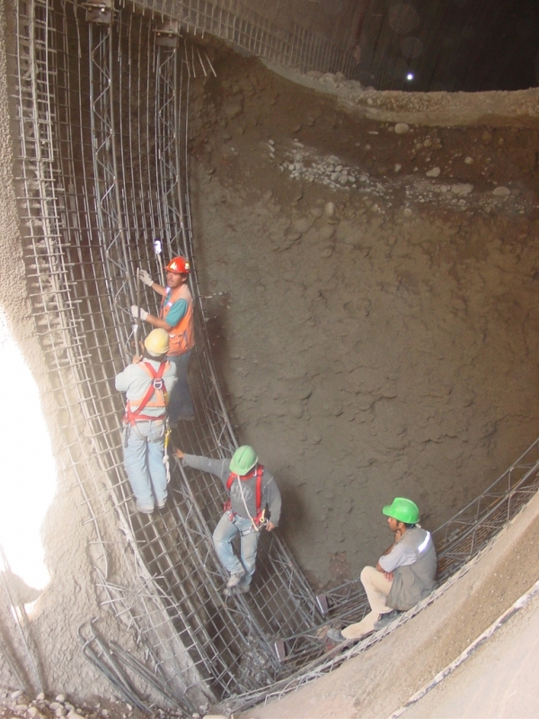
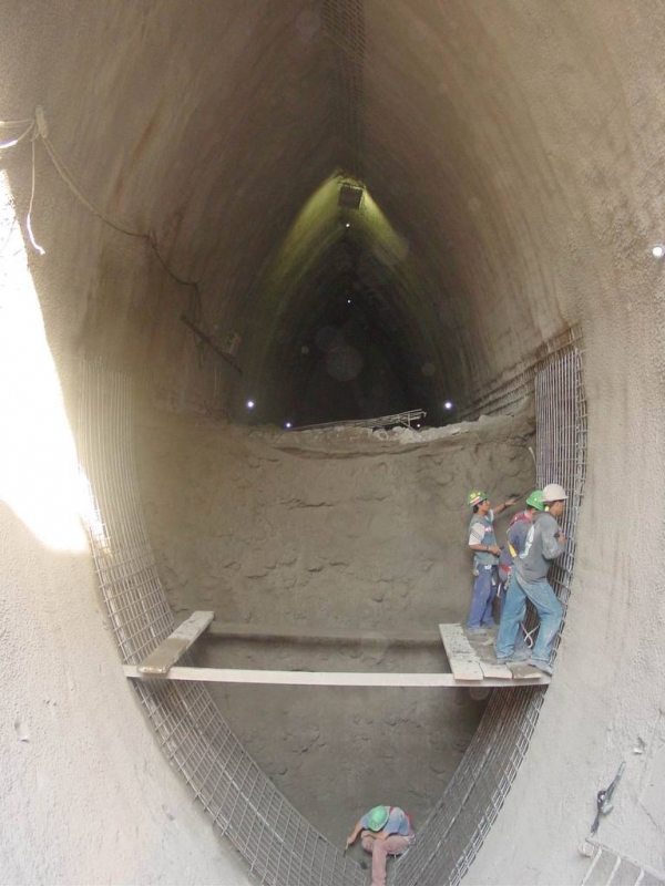
The Wayside ventilation shaft is one of five needed to provide ventilation and emergency access for the London Tunnels section of the Channel Tunnel Rail Link. The tunnels were designed as permanent sprayed concrete-lined, constructed in two phases, temporary primary and permanent secondary linings. The required watertightness will be achieved by staggering the joint locations between the two linings, utilising internal curing agents and steel fibres in the secondary lining sprayed concrete and using injectable flexible tubes in the joints of the secondary lining.

Activity
Categories
3D model of tunnel structure
Secant pile wall
Plan of Tunnel Structure
Construction Site
Surface View from Shafthead
Breakout of Cross Adit
Project number
342D
Final cost
£50 million GBP

Pages