Main Menu

You are here

Shaft

North Yorkshire Polyhalite Project

Client
Service Performed
Dr. Sauer & Partners provided commercial support, SCL design verification and functioned as a mediator between Sirius Minerals’ mining and construction team.
Commencement - Services
April 01, 2019
Completion - Services
October 31, 2019
Location
Whitby
Yorkshire
YO11 3ZB
United Kingdom
Geology description

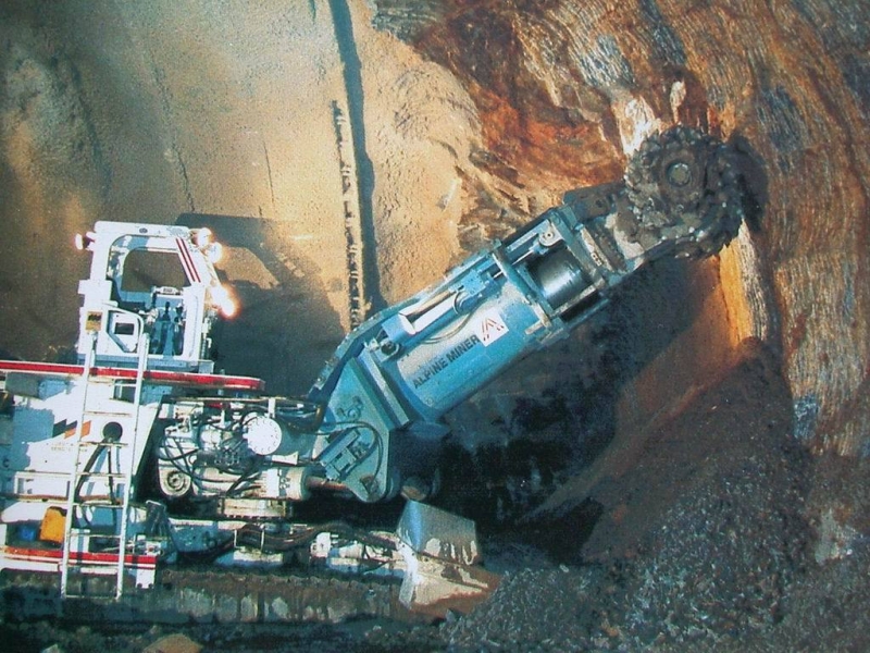
Most of the MTS is developed within the Redcar Mudstone Formation. It comprises alternating layers of silty mudstone and clayey siltstones with subordinated thin beds of limestone and sandstone.

Bands of ironstone nodules and fossil shells as well as pyrite are present in places. Multiple major fault systems were identified that cut the MTS alignment. 

Geology types
Description

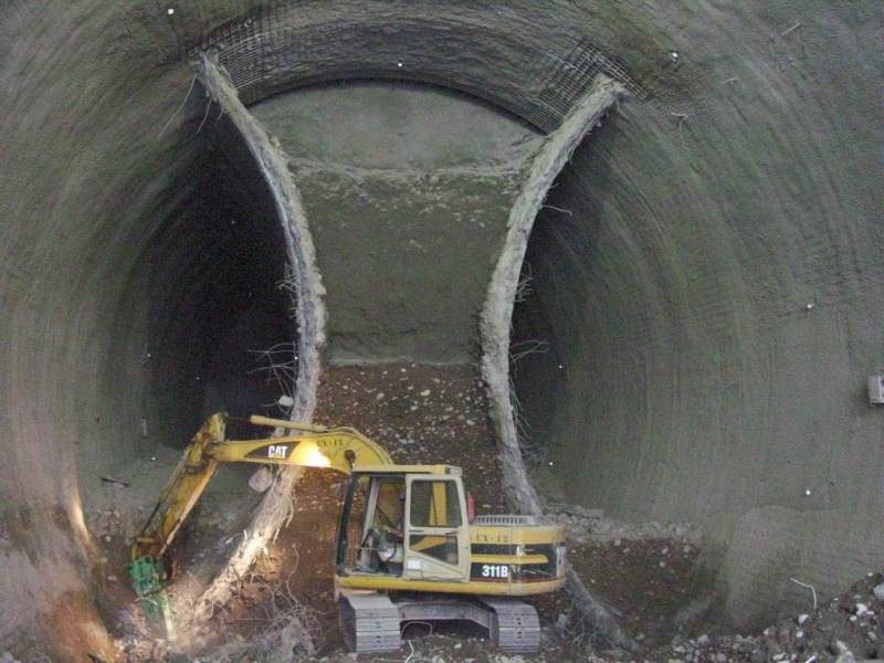
North Yorkshire holds one of the largest, high grade polyhalite reserves worldwide. It is located within the North York Moors National Park, ca. 1800m below surface. Once processed, this mineral functions as an organic fertilizer to boost harvest. Sirius Minerals plc are currently developing the infrastructure to mine the polyhalite. This operation requires deep shafts to access the mineral body but also demands an extensive mass transport system (MTS) to keep the impact on the National Park to a minimum. Therefore, at ca. 350m below surface, a series of SCL tunnels link the deep shafts to a conveyor belt system, which again connects the mining operation via a 37km TBM tunnel to its material handling facility.

Activity
Categories
Construction methods
Tunnel length
37km
Project overview
Woodsmith mine site close to Whitby
Project number
515C
Final cost
£4.2 billion GBP

Velenje-Shaft

Service Performed
NATM Design, In-Situ Measurement, Site Supervision
Commencement - Services
February 29, 1988
Completion - Services
September 30, 1989
Location
Ljubljana
Slovenia
Technical data

Inclined shaft, diameter 4.3 m, L = 40 m. NATM Test tunnel, heavy support.

Geology description

Schist, clay, sand and coal.

Geology Type: Soft Ground

Geology types
Description

NATM test tunnel, heavy support Aligning pole (d= 5 cm) should make deformations possible.

Categories
Shaft

New Studley Water Tunnel

Service Performed
NATM design, construction supervision and instrumentation
Commencement - Services
January 29, 1988
Completion - Services
December 29, 1990
Location
Birmingham
United Kingdom
Technical data

Large diameter shaft constructed using NATM for the diversion of a Water Supply Tunnel.

Geology description

Sandstone, Shale / Marl, Limestone

Geology Type: Hard Rock

Geology types
Categories
Shaft
Final cost
$25,000,000
Shotcreting
Overview drawing
Overhead View of Shaft and Water Tunnel
British Construction Award 1989

Southport Deep Shaft

Service Performed
NATM design and construction supervision
Location
Southport
United Kingdom
Technical data

9 m (29.5 ft) excavated dia. 80 m (262 ft) deep vertical shaft for sewage treatment. Upper 28 m (92 ft) of shaft excavation supported using diaphragm walls with the remaining 52 m (170 ft) excavated using NATM with a reinforced shotcrete primary lining. Permanent lining comprises slipformed reinforced concrete.

Geology description

Beach Sand overlying Mercia Mudstone overlying Halite (rock salt).

Geology types
Categories
Shaft
Sahft wall, support elements
Plan View
Cross Section
Overhead View showing Shaft
View from the Shaft Base
Work at Shaft Base
Reinforcement before Shotcrete Lining Installation
Shaft at the Surface
One Round of Shaft Excavation Completed
Crane at Shaft Surface

C103 Escape Shafts

Service Performed
Design of Temporary Support
Commencement - Services
May 01, 1996
Completion - Services
December 01, 1996
Location
London
United Kingdom
Technical data

Design of temporary shotcrete lining (150 mm thick) to support excavation for a perimiter r.c. beam at the base of the escape shaft piled walls. Shotcrete required to support the ground due to the foundations of a live railway viaduct located 2 m from the shaft walls.

Geology description

Made Ground, Alluvium/Terrace, Gravels London Clay

Categories
Shaft

Hampton Water Treatment Works - C079 Hampton Ozonation

Service Performed
Design and Detailing of Shaft, Base and Breakouts
Commencement - Services
December 31, 1996
Completion - Services
December 31, 1997
Location
Hampton
Middlesex
United Kingdom
Technical data

10.3 m ID shaft, 33.5 m deep with a sprayed concrete (fcu 25 N/mm²), shell 250 mm thick. Two breakout eyes at base level, with 3.73 m diameter 400 mm thick collars.

Geology description

Made Ground, Sand/Gravel Clay (London Clay) Water table at 1.26 m below ground level.

Geology types
Categories
Shaft

Brixton Station Improvement

Service Performed
Design of a MIP Lift Shaft and Access Cross Passages to Existing Station Platform
Commencement - Services
March 21, 1999
Completion - Services
January 01, 2001
Location
London
United Kingdom
Technical data

New subway station platform access shaft. Connection from main ticket hall to underlying (bi-secting) platform cross adit (cast iron liner breakout). The design accommodates difficult existing station (spatial) encroachments by utilizing an elliptical shape with changes in size, axis and shape (from 3m to 6.5m).

Geology description

London Clay overlaying Reading Beds at depth.

Categories
Shaft

Channel Tunnel Rail Link - Corsica Street Ventilation Shaft and Tunnels

Service Performed
Design services and technical support during construction.
Commencement - Services
August 27, 2001
Completion - Services
May 27, 2002
Location
73 Collier St
London
N1 9BE
United Kingdom
Technical data

Main Shaft: 18 m (59 ft) dia., depth 30 m (98 ft); Inspection Shaft: 11m (36 ft) x 7 m (23 ft) elliptical, depth 10 m ; Ventilation tunnel: width: 6 m(20 ft) x height: 12 m (39 ft) elliptical.

Geology description

London clay with sand lenses.

Geology types
Description

The Corsica Street Ventilation Shaft comprises the permanent pressure relief and ventilation adit connecting the down line running tunnel to the shaft and temporary access adit tunnel. The ventilation adit was designed as a permanent sprayed concrete lined tunnel built in two phases: primary and secondary linings. The required watertightness was reached by staggering the joint locations between primary and secondary linings, utilising internal curing agents and steel fibres in the secondary lining sprayed concrete and injecting flexible tubes into joints of the secondary lining.

Activity
Categories
Shaft
Final cost
$110,000,000
Construction site
Breakout from shaft
3D Model of tunnels and shaft
Shaft Base
Excavation of Service Tunnel
Exacvation of Cross Adit
Bench and Invert Excavation
Formwork for Final Lining
Excavation steps
Lattice Girder, Wire Mesh and Shotcrete Detail
Excavation and support steps
Shotcreting of 2nd layer
Lattice Girder installation
Lattice girder, wire mesh and shotcrete
Block-out in shaft lining for tunneling
Excavation for the collar
Reinforcement for the shotcrete collar
Shotcreting of the collar
Project number
340E
Final cost
£110 million GBP

Channel Tunnel Rail Link - Wayside Ventilation Shaft and Tunnels

Client
Service Performed
NATM alternative design and site supervision.
Commencement - Services
February 25, 2002
Completion - Services
October 20, 2003
Location
1 Kemble St
London
WC2B 4AN
United Kingdom
Technical data

2 ventilation tunnels: 32 m² (344 sqft), 2 enlarged ventilation tunnels: 38 m² (409 sqft), 2 drop shafts: 75 m² (807 sqft), 1 horizontal and inclined emergency intervention tunnel: 19 m² (205 sqft), 1 horizontal cross passage chamber: 31 m² (334 sqft) with 4 cross adits underlining the London - Tilbury railway lines.

Geology description

Made ground, terrace gravel, London Clay formation; groundwater level 1m bgl; cover to terrace gravel less than 3m.

Geology types
Description

The Wayside ventilation shaft is one of five needed to provide ventilation and emergency access for the London Tunnels section of the Channel Tunnel Rail Link. The tunnels were designed as permanent sprayed concrete-lined, constructed in two phases, temporary primary and permanent secondary linings. The required watertightness will be achieved by staggering the joint locations between the two linings, utilising internal curing agents and steel fibres in the secondary lining sprayed concrete and using injectable flexible tubes in the joints of the secondary lining.

Activity
Categories
Shaft
3D model of tunnel structure
Secant pile wall
Plan of Tunnel Structure
Construction Site
Surface View from Shafthead
Breakout of Cross Adit
Project number
342D
Final cost
£50 million GBP

Chambers Creek Tunnel Access Shafts

Service Performed
Consulting and site supervision for shotcrete lining installation
Commencement - Services
July 30, 2000
Completion - Services
December 30, 2001
Location
Tacoma, WA
United States
Technical data

3 shafts, 12 ft (3.7 m) ID, 40 ft (12 m) to 130 ft (40 m) deep with a sprayed concrete (fcu 25 N/mm²) shell, 6 inches (150 mm) thick. Breakout into a combined sewer line at the bottom of the shaft.

Geology description

Sand / Gravel Clay, galical deposits. Water table at 110 ft (33.5 m) below ground level.

Geology types
Categories
Shaft
Final cost
$1,500,000
Surface around Shaft Head
Shaft at Surface
View from Base of Shaft

Pages