Main Menu

You are here

Inspection & Maintenance

Puerto Suello Hill Tunnel

Service Performed
Tunnel inspection, structural analysis and assessment, recommendations and concepts for tunnel repair and retrofit.
Commencement - Services
April 01, 2010
Completion - Services
July 01, 2015
Location
San Rafael
San Rafael, CA 94901
United States
Geology description

The bedrock in the project area primarily comprises intact metamorphosed sandstone (i.e. graywacke) of the Franciscan Melange and contains few discontinuities. The bedrock is typically overlain by stiff to hard lean clay.

Geology types
Description

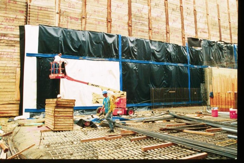
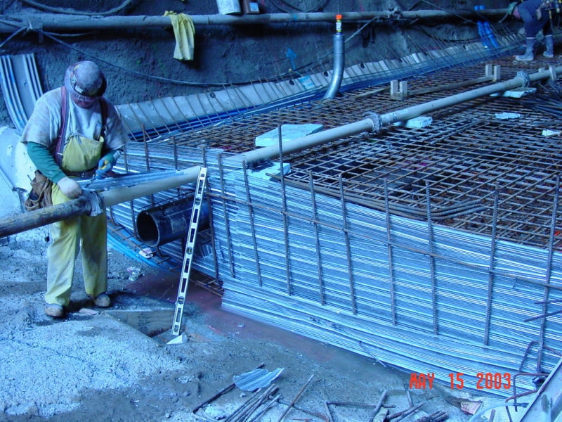
The Puerto Suello Tunnel is a 400 m long single-track rail tunnel in San Rafael, California and was constructed in 1879. The 4.9 m wide and 6.8 m high tunnel was partially destroyed by a fire in 1961, was rebuilt for freight service in 1967 and closed in the mid-1980s. The tunnel was acquired by SMART in 2003, who retrofitted and then reopened it for commuter rail service in 2017.

The ground overburden above the tunnel reaches a maximum of 45 m and the tunnel was constructed using cut-and-cover and mined construction methodologies.

Activity
Service areas
Inspection & Maintenance, Rehabilitation & Tunnel Widening
Construction methods
Puerto Suello Hill Tunnel reopened in 2017 (www.wikipedia.org)
One of the developed repair options
Project number
429C
Project Type
Final cost
$3 million USD

Lima Metro Line 2

Service Performed
Investigation of unexpected progressing settlement of ground surface and constructed Metro Line 2 tunnel, shaft and station structures in Lima’s Santa Anita district.
Commencement - Services
March 01, 2014
Location
Av. Aviación 2494 – San Borja
Lima
Peru
Geology description

All Metro Line 2 structures in the Santa Anita district were constructed in dense gravels which is underlain by a sequence of clay, sand and gravel layers. The bedrock lies an assumed 30m to 150m below ground surface.

Geology types
Description

Lima's Metro Line 2 project comprises 27 km of all-underground Line 2, plus an 8 km underground spur to the airport which will make up the first section of Line 4. Thirty-five new stations are being constructed, seven of them mined and the rest constructed by cut and cover. The MDL2 consortium is to design, finance and build the new line and to operate and maintain it for the following 30 years.

Activity
Service areas
Construction methods
Overview of Lima's Metro Line 2 project (www.thinglink.com)
Results plot of the 2D finite element consolidation analysis
Project number
473C
Project Type
Final cost
$5.7 billion USD
Completion date
Ongoing

Bank Station Capacity Upgrade - Defects Survey

Service Performed
Defects surveys of the London Underground existing facilities predicted to settle 1 mm or more due to the planned station upgrade works.
Commencement - Services
August 01, 2013
Completion - Services
May 01, 2022
Location
London
London
EC3V 3LA
United Kingdom
Geology description

The geology comprises London Clay formation overlain by Quaternary superficial deposits and made ground.

Geology types
Description

Bank Station is a London Underground station located in the City of London financial district. It is a key interchange served by five existing lines. The Bank Station Capacity Upgrade (BSCU) comprises the construction of new tunnels adjacent to and connecting with the existing tunnels. Defects surveys of the LU existing facilities predicted to be impacted by the BSCU works had to be carried out before construction started. All existing facilities expected to be within the 1 mm settlement contour were inspected for defects.

Activity
Service areas
Inspection & Maintenance
Construction methods
Tunneling under
Defects survey in the existing running tunnel
Defects survey on the existing station platform
Project number
451C1
Final cost
£563.8 million GBP

Bank Station Capacity Upgrade - Impact Assessment

Service Performed
Assessment of the impact on existing cast-iron and precast concrete tunnel linings (in total approximately 300 assets.) including empirical and finite element calculations.
Commencement - Services
January 01, 2013
Completion - Services
May 01, 2022
Location
London
London
EC3V 3LA
United Kingdom
Geology description

The geology comprises London Clay formation overlain by Quaternary superficial deposits comprising river terrace deposits and alluvium which are generally overlain by made ground.

Geology types
Description

Bank Station is a London Underground station located in the City of London financial district. It is a key interchange served by five existing lines. The Bank Station Capacity Upgrade (BSCU) comprises the construction of new tunnels adjacent to and connecting with the existing tunnels. A staged, risk-based approach was used to efficiently assess the affected existing assets and determine an appropriate mitigation and monitoring scheme. Empirical methods and complex numerical models were used at the different stages of the assessment, to understand the risk to the existing railway and how they could best be managed while minimizing disruption to the station and its users.

Activity
Service areas
Inspection & Maintenance
Construction methods
Tunneling under
Existing escalator at Bank Station
FE model of existing (green) and new (red and pink) structures
Project number
451D_1
Final cost
£563.8 million GBP
Completion date
Ongoing

Luck Stone Fairfax Plant – Inspection Works

Service Performed
In-depth inspection of a connector tunnel in accordance with TOMIE manual and the SNTI manual of the U.S. Department of Transportation - FHWA.
Commencement - Services
July 01, 2016
Completion - Services
July 31, 2016
Location
15717 Lee Hwy
Centreville, VA, VA 20121
United States
Geology description

The prevalent rock type of the tunnel is diabase. The rock mass is moderately jointed, with closely to very closely spaced joints. The rock is slightly weathered.

Geology types
Description

Inspected tunnel connects two quarries at the Luck Stone Corporation Fairfax plant. The tunnel crosses beneath the Lee Highway (US Route 29), in a North-South direction. Built ca. 1975, the tunnel is partially unlined and in rock; approx. 190 feet long and approx. 22 feet wide and 22 feet high. As the Northern quarry side is already exhausted, the tunnel is rarely used with just one or two transits per day.
Dr. Sauer & Partners performed an in-depth inspection of a connector tunnel; assessed the tunnel condition and provided remedial measures.

Activity
Service areas
Inspection & Maintenance
Construction methods
Tunneling under
Connector Tunnel - North Portal / Highwall
Connector Tunnel - South Portal / Highwall
Project number
242E1
Final cost
n/a

Eglinton Crosstown LRT – Inspection Works

Service Performed
Initial and detailed inspection of underground structures. Condition assessed and rated according to the 'Highway and Rail Transit Tunnel Inspection Manual (2005)' of the U.S. Department of Transportation - FHWA.
Commencement - Services
January 01, 2016
Completion - Services
December 01, 2019
Location
Yonge Street
Toronto, ON M4S2C6
Canada
Geology description

The geology comprises heavily over-consolidated hard plastic glacial till layers, stratified deposits of stiff to hard clays and dense, non‐plastic, silt and sand.

Geology types
Description

The Crosstown LRT Project is a Light Rail Transit Line that will run along Eglinton Avenue between Mount Dennis and Kennedy Station. This 19km corridor will include a 10km underground section between Keel Street and Laird Drive. This section comprises 2 bored running tunnels; 12 stations of which 3 (Laird, Avenue and Oakwood) will be built underground using the SEM method; 12 cross passages connecting the bored running tunnels and 3 emergency exit buildings. Dr. G. Sauer & Partners performed an initial, detailed inspection of the bored running tunnels, every cross passage and every emergency exit building to establish the condition of these structures prior to takeover by CTS.

Activity
Service areas
Inspection & Maintenance
Construction methods
Inspection of the Segmental Tunnel Lining
Inspection of the Cross Passage Entrance
Project number
467E1
Final cost
$8.25 billion CAD
Completion date
Ongoing

Velenje-Shaft

Service Performed
NATM Design, In-Situ Measurement, Site Supervision
Commencement - Services
February 29, 1988
Completion - Services
September 30, 1989
Location
Ljubljana
Slovenia
Technical data

Inclined shaft, diameter 4.3 m, L = 40 m. NATM Test tunnel, heavy support.

Geology description

Schist, clay, sand and coal.

Geology Type: Soft Ground

Geology types
Description

NATM test tunnel, heavy support Aligning pole (d= 5 cm) should make deformations possible.

Categories
Service areas
Inspection & Maintenance, Site Supervision & CM, QA/QC

WMATA Red Line - Waterproofing Concept

Service Performed
Service Establishing a membrane based waterproofing system for a running tunnel rehabilitation incl. feasibility and construcibility.
Commencement - Services
September 26, 1987
Completion - Services
May 01, 2002
Location
Washington, DC
United States
Technical data

Several running tunnels of the WMATA Red Line in Washington, DC, constructed in the 1970s using both drill and blast and TBM excavation method.

Geology description

Piedmont Geolgic Plain, shallow crystalline bedrock with a high permeability.

Description

The Washington Metropolitan Transit Authority (WMATA) faces serious problems related to water intrusion in sections of the Red Line. Especially in the Northwestern Section water leakage by far exceeds the acceptable limits. The consequences include electrical malfunctions, icing and clogging of the drainage system as well as deterioration of the tracks and the utilities in the tunnels. They are detrimental to an efficient operation and represent considerable safety hazards. The report describes a permanent, none adhesive waterproofing layer system for the rehabilitation of the WMATA Red Line tunnels and underground structures. It shows the feasibility and constructibility of the selected approach for a single tunnel and shaft, similar solutions will be developed for adits, crossovers, etc.

Categories
Service areas
Inspection & Maintenance
Waterproofing Drawing
Waterproofing installed onto roof slab
Installation of the PVC-Membrane in the air duct
Rehabilitation Work Schedule
Waterproofing Concept Shaft
Rehabilitation Work Section
Rehabilitation Work Schedule

MBTA, Russia Wharf Segment, Section CC03A

Service Performed
NATM detailed design and site supervision during construction.
Commencement - Services
December 28, 1996
Completion - Services
December 19, 2004
Location
Boston
Boston, MD 02101
United States
Technical data

Road tunnel with 2 lanes and a lenght of 400 ft. Study into the construction of either a single tunnel or a binocular tunnel with central pier using the shotcrete support method with ground freezing pre-support to protect overlying historic building.

Geology description

Made ground, peat, glacial till (cohesive, plastic). The peat horizon undulates along the route, in places it is expected to be exposed in the top half of the proposed tunnel face.

Geology types
Description

The Russia Wharf segment is the last, but most challenging section of the Silverline Phase II construction for the Massachusetts Bay Transportation Authority (MBTA). The line is designed to provide a dualmode bus rapid transit connection between the central business district in South Boston to the new Convention Center. The tunnel passes diagonally under the 100 year old Russia Wharf complex, which comprises three seven-story buildings with steel frames and brick facades listed in the National Register of Historic Places. The chosen construction method was NATM in conjunction with ground freezing, for the first time in the US. Steel fibre reinforced concrete was used for temporary and permanent lining.


Final cost
$18,000,000
Construction methods
Special Construction techniques
Tunneling under
Groundwater control
 Overview of West Cofferdam
Sheet Pile Wall
Excavation of T.H. first round
Reflectors for the monitoring
4 Bar L.G.
Short tunneling
Steel pile for underpinning
Close up of L.G.
Convergence Bolt before schotcreting
4 Bar longitudinal L.G.
Shotcrete at the face of T.H. & Bench
Installation of spiles
Spiles installed
Spiles installed
Wood piles
Installation of Spiles
Excavation of Invert
 Pile Shoe Reinforcement in T.H.
L.G & Wire Mesh installed
Butt plate connection
L.G & Wire mesh, Wood piles,Pile for underpinning
Wood files
Shotcreting, Pile for Underpinning
Overview of west Cofferdam
Overview of "Russia Wharf Building"
L.G & Wire Mesh, Pile for underpinning
L.G. installation
Pile Shoe reinforcement in T.H
View of tunnel and Graphic Arts Building
L.G. & Wire Mesh at Portal Area
Wood Piles, Pile for Underpinning
Compressible Pad onto wood piles
Wood piles, piles for underpinning
Profiling in T.H using Roadheader
View of "Russia Wharf Buildings"
Wood piles, Piles for underpinning
Shotcreting
Waterproofing at Invert, Water Barriers
Installed Waterproofing, Formwork for Center Wall
Installation of Rebar Spile
L.G & Wire Mesh installed, Shotcrete Invert in T.H.
Overview Tunnel Inside
L.G. & Wire Mesh, Piles for Undpinning
L.G. & Wire Mesh, Halfenbox
Shotcrete Tunnel completed
Grouting of Spiles completed
Waterproofing installed at Invert, Halfenbox
Reinforcement of center wall
Reinforcement of a Blockout in the center wall
Pouring concrete of Invert
Invert
Welding operation
Control & Grouting Pipe, Reinjectable Hose
Control & Grouting Pipe, Fuco Hose
Top of Centerwall
Reinforcement of Shotcrete
Installation of L.G. 1st round
Excavation of 2nd half of Binocular T.
Shotcrete F.L., Center wall
Binocular Tunnel
Installation of spiles
Freezing Pipes
Freezing Pipes
1st half of binocular T.
Pile shoe reinforcement in T.H.
Plan View of the Binocular Tunnel
Tower Crane View
Tower Crane View of Russia Wharf Complex
Longitudinal Section for the Binocular Tunnel
Binocular Tunnel Section
Ground Freezing Tubes and Settlement Compensation under Russia Wharf
Top Heading Excavation cutting old wooden support piles
Reinforcing and Encasing cutted wooden Piles
Reinforcement of Middlewall of Binocular Tunnel
Excavation of the second Tube of the Binocular Tunnel
Waterproofing of the Binocular Tunnel
Freezing Pipes at surface
Shoe reinforcementon timber piles
Project number
263D
Final cost
$18 million USD

Gannett Fleming PTC

Service Performed
Tunnel Inspection Services – Ventilation System Improvement Study
Estimated cost
$57,000
Commencement - Services
October 01, 1994
Location
Harrisburg, PA
United States
Technical data

Inspection of tunnel roof slab structure, existing ventilation system and safety/traffic flow monitoring systems. Produced Detailed Report including following: 1. Inspection report on existing tunnel conditions. 2. Longitudinal Ventilation System Study 3. Design of remedial waterproofing system with three alternatives. 4. Cost estimates for various alternatives/measures. Two lane highway tunnel located on the Pennsylvania Turnpike I-76, constructed in 1940, total length: 1,16 mile (1867m).

Activity
Service areas
Inspection & Maintenance