Main Menu

You are here

Cut & Cover

Eglinton Crosstown LRT – Site Supervision

Service Performed
Detailed 24/7 supervision and engineering support for three SEM stations in soft ground; namely Laird, Avenue and Oakwood.
Commencement - Services
November 01, 2015
Completion - Services
December 01, 2021
Location
97 Front Street West
Toronto, ON M5J1E6
Canada
Geology description

Glacial depositional systems created a complex distribution of heavily overconsolidated till layers, separated by interstadial stratified deposits of glaciolacustrine clay, silt, and sand.

Geology types
Description

The Crosstown is a light rail transit line, which is part of the regional transportation plan for the Greater Toronto and Hamilton Area. The project will provide a 19km corridor across Eglinton Avenue, connecting ten stops and 15 underground stations with a 10km twin-bored tunnel. Dr. G. Sauer & Partners provided detailed design for Laird, Avenue and Oakwood stations. A combination of Cut-and-Cover construction for the shafts and mined technique (SEM) for the tunnels has been utilised. The 24/7 supersvision services provided engineering support, detailed inspection and documentation by a team of eperts for each of the three stations.

Activity
Construction methods
Cut & Cover, NATM
Tunneling under
Route map (www.thecrosstown.ca)
Laird Station Excavation
Project number
467E
Project Type
Final cost
$8.25 billion CAD

Puerto Suello Hill Tunnel

Service Performed
Tunnel inspection, structural analysis and assessment, recommendations and concepts for tunnel repair and retrofit.
Commencement - Services
April 01, 2010
Completion - Services
July 01, 2015
Location
San Rafael
San Rafael, CA 94901
United States
Geology description

The bedrock in the project area primarily comprises intact metamorphosed sandstone (i.e. graywacke) of the Franciscan Melange and contains few discontinuities. The bedrock is typically overlain by stiff to hard lean clay.

Geology types
Description

The Puerto Suello Tunnel is a 400 m long single-track rail tunnel in San Rafael, California and was constructed in 1879. The 4.9 m wide and 6.8 m high tunnel was partially destroyed by a fire in 1961, was rebuilt for freight service in 1967 and closed in the mid-1980s. The tunnel was acquired by SMART in 2003, who retrofitted and then reopened it for commuter rail service in 2017.

The ground overburden above the tunnel reaches a maximum of 45 m and the tunnel was constructed using cut-and-cover and mined construction methodologies.

Activity
Construction methods
Cut & Cover, NATM, SCL
Puerto Suello Hill Tunnel reopened in 2017 (www.wikipedia.org)
One of the developed repair options
Project number
429C
Project Type
Final cost
$3 million USD

Lima Metro Line 2

Service Performed
Investigation of unexpected progressing settlement of ground surface and constructed Metro Line 2 tunnel, shaft and station structures in Lima’s Santa Anita district.
Commencement - Services
March 01, 2014
Location
Av. Aviación 2494 – San Borja
Lima
Peru
Geology description

All Metro Line 2 structures in the Santa Anita district were constructed in dense gravels which is underlain by a sequence of clay, sand and gravel layers. The bedrock lies an assumed 30m to 150m below ground surface.

Geology types
Description

Lima's Metro Line 2 project comprises 27 km of all-underground Line 2, plus an 8 km underground spur to the airport which will make up the first section of Line 4. Thirty-five new stations are being constructed, seven of them mined and the rest constructed by cut and cover. The MDL2 consortium is to design, finance and build the new line and to operate and maintain it for the following 30 years.

Activity
Construction methods
Cut & Cover, NATM, SCL
Overview of Lima's Metro Line 2 project (www.thinglink.com)
Results plot of the 2D finite element consolidation analysis
Project number
473C
Project Type
Final cost
$5.7 billion USD
Completion date
Ongoing

Sound Transit Beacon Hill Station

Service Performed
Optimizing station and tunnel configurations, Interpreting geologic information, preliminary and detailed design, developing 3D Finite Element Models and performing structural and seismic design.
Commencement - Services
January 01, 2002
Completion - Services
January 01, 2009
Location
401 S. Jackson Street
Seattle, WA 98104
United States
Geology description

Beacon Hill Station is located 49 m below the ground surface in complex glacial soils with multiple groundwater horizons.

Geology types
Description

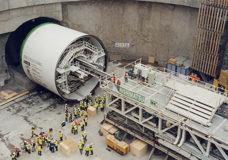
Beacon Hill Station is part of the 22.5 km initial segment of Sound Transit's Central Link Light Rail. It is located 49 m below the ground surface in complex glacial soils with multiple groundwater horizons. The project comprises deep mined station tunnels and two 1.5 km long running tunnels excavated using a tunnel boring machine. The mined station was excavated through compressible glacial soils with multiple groundwater horizons using conventional mining techniques. The access shafts and station headhouses were constructed using slurry walls and cut-and-cover techniques.

Activity
Construction methods
Cut & Cover, NATM
Special Construction techniques
Tunneling under
Tunnel length
1.5km
Beacon Hill Station Layout
Tunnel Excavation under way
Project number
418C
Final cost
$250 million USD

Tottenham Court Road Station Upgrade Design

Client
Service Performed
Design of numerous temporary sprayed concrete lined shaft and tunnel structures, and the waterproofing system for the upgrade of the existing London Underground Tottenham Court Road Station.
Commencement - Services
August 01, 2007
Completion - Services
January 01, 2010
Location
Oxford Street
London
London
W1D 1AN
United Kingdom
Technical data

Tottenham Court Road Station is a London Underground station situated in central London. The station serves as an interchange between the Central and Northern lines. Over 150,000 passengers use the station daily.

Geology description

London Clay Formation (over-consolidated, very stiff to hard clay)

Geology types
Description

Currently over 150,000 passengers use the station daily and with the completion of Crossrail in 2017, passenger numbers are expected to increase to over 200,000. The tunnels are of diameters between 4.0m and 11.0m and typically consist of a temporary sprayed concrete primary lining, a spray applied waterproofing membrane and a cast-in-place concrete secondary lining. Multiple transitions and interfaces to existing LU structures make for a challenging design and construction project under the busy streets of central London.

Activity
Final cost
$480,000,000
Construction methods
Cut & Cover
Special Construction techniques
Tunneling under
Max Excavation Area (m2)
23-104m2
Tunnel length
13-104m
Overview of new tunnel works
General arrangement of sprayed concrete overbridge
Northern line concourse tunnel with cross passages
Installation of steel transfer beam
Excavation and support of Northern line concourse tunnel
Removal of existing backfilled structure
Project number
411D
Final cost
£480 million GBP

Dublin Port Tunnel

Service Performed
NATM support works
Commencement - Services
December 30, 2001
Completion - Services
December 29, 2005
Location
Dublin
Dublin
Ireland
Technical data

Bi-directional two lane road tunnels encompassing 5.6 km area. Total tunnel lenght: 4.5 km, TBM bored lenght: 2.4 km, each tube at 11.7 m diameter, Cut & Cover: 1.5 + 0.6 km.

Geology description

Dublin Boulder Clay (lodgement till), carboniferous argillaceous, limestone bedrock.

Geology types
Description

The Dublin Port Tunnel is an approximately 3.5 mile long twin, two-lane tunnel which connects the M50 motorway and Dublin Airport with Dublin Harbour. The underground connection will help to manage the rising traffic demands and will carry up to 20,000 vehicles per day upon opening. The overall scheme consists of 2.8 miles of tunnels, where 1.3 miles are Cut-and-Cover and the remaining 1.5 miles are TBM bored 35ft.

Final cost
$5,000,000
Construction methods
Cut & Cover, TBM
Tunneling under
Cut & Cover at Alfie Byrne Road
TBM Launch Pit
Formworks for Cut & Cover Section
Construction of Reception Shaft
Open Face TBM
Single Pass Lining Installation
Project number
214E
Final cost
£385 million GBP

Beacon Hill Station

Service Performed
NATM / SEM station design and construction supervision.
Estimated cost
$250,000,000
Commencement - Services
February 26, 2000
Completion - Services
December 28, 2007
Location
401 S. Jackson Street
Seattle, WA 98104
United States
Technical data

NATM Light Rail Station located 150 ft (46 m) beneath surface. Station complex includes central elevator/access shaft, concourse, opposing platform tunnels and cross passages. Platform Tunnel Section: 36 ft w x 31 ft h; Platform Tunnel Area: 925 sqft (86 m²); total Station Excavation Area: 63,000 sqft (5853 m²).

Geology description

Over-consolidated glacial clay and till with fracutured zones. Intermittent sand and silt layers with perched groundwater.

Geology types
Description

The Beacon Hill Tunnels and Station are part of the 22.5km initial segment of the Sound Transit Central Link Light Rail Line that will establish a high capacity commuter connection from downtown Seattle to Tacoma. The 1300m running tunnel under Beacon Hill will be mined by Earth Pressure Balance Machine (EPB), while the deep mined Station will be constructed using slurry walls and the New Austrian Tunneling Method (NATM), referred to as Sequential Excavation Method (SEM) for this project.

Activity
Bid cost
$280,000,000
Final cost
$280,000,000
Construction methods
Cut & Cover, NATM, TBM
Tunneling under
Max Overburden
Min:120 Max:140
Beacon Hill Station layout
Tunnel excavation under way
3D rendering of Beacon Hill Station complex
Platform tunnel cross section
Schwind Thomas
Installation of Vacuum Dewatering
Rendering of Beacon Hill Station
Project number
325
Final cost
$280 million USD

North Shore Connector

Service Performed
Alternative NATM tunnel design, cost estimate & finite element analysis.
Commencement - Services
July 01, 2002
Completion - Services
January 01, 2008
Location
Alpha Dr, Harmar Township
Pittsburgh, PA 15238
United States
Technical data

NATM running tunnel connecting Convention Center station with surface to be constructed beneath historic downtown structures as part of existing LRT system expansion. Provided initial design package, including detailed cost estimate. Tunnel Length: ~446'* Cross Section: 41'-4" x 26'-11"; 895.24 ft^3 *Including widening zone for track cross-over.

Geology description

Fill, alluvium (granular and cohesive), fluvioglacial deposits and bedrock.

Geology types
Description

The North Shore Connector Project consisted of three underground station structures and running tunnels, excavated with TBM and Cut-and-Cover tunneling methods. It also included a twin bore tunnel under the Allegheny River. Dr. Sauer and Partners provided design review and design support services. The development of the waterproofing system for underground structures including tying into an existing station using a flexible membrane system, combined with a sectioning system that allows for section grouting instead of the entire structure if a leak is detected was also provided.

Activity
Final cost
$7,600,000
Construction methods
Cut & Cover, NATM
Project overview
Cut-and-Cover method
Project number
361D
Final cost
$7.6 million USD