Main Menu

You are here

Waterproofing

Section E4a, Greenbelt Route, Georgia Avenue - Petworth Station

Service Performed
Waterproofing design and construction support services
Commencement - Services
December 28, 1994
Completion - Services
December 28, 1997
Location
Washington, DC
United States
Technical data

PVC membrane waterproofing Cut & Cover Station, including crossover, service rooms, ventilation structures, station entrances. Overall length: 1,090 ft (332 m); average depth: 75 ft (23 m); waterproofed area: 275,000 sqft (25550 m²).

Geology description

Very compact light gray clayey or silty medium fine sand. Dark gray plastic clay. Light gray/green fine grained hornblende quartz diorite, highly weathered to slighty weathered.

Geology types
Categories
Waterproofing
Final cost
$1,200,000
Installation at the wall
Waterproofing at TBM portal
Airial photo
Running Tunnels entering the Station Shaft
Installation of Running Tunnel Waterproofing System
Waterproofing System at Junction Running Tunnel and Station Shaft
Construction of Cut & Cover Section
Doorframe Slab Cross Section and Plan

WMATA Red Line - Waterproofing Concept

Service Performed
Service Establishing a membrane based waterproofing system for a running tunnel rehabilitation incl. feasibility and construcibility.
Commencement - Services
September 26, 1987
Completion - Services
May 01, 2002
Location
Washington, DC
United States
Technical data

Several running tunnels of the WMATA Red Line in Washington, DC, constructed in the 1970s using both drill and blast and TBM excavation method.

Geology description

Piedmont Geolgic Plain, shallow crystalline bedrock with a high permeability.

Description

The Washington Metropolitan Transit Authority (WMATA) faces serious problems related to water intrusion in sections of the Red Line. Especially in the Northwestern Section water leakage by far exceeds the acceptable limits. The consequences include electrical malfunctions, icing and clogging of the drainage system as well as deterioration of the tracks and the utilities in the tunnels. They are detrimental to an efficient operation and represent considerable safety hazards. The report describes a permanent, none adhesive waterproofing layer system for the rehabilitation of the WMATA Red Line tunnels and underground structures. It shows the feasibility and constructibility of the selected approach for a single tunnel and shaft, similar solutions will be developed for adits, crossovers, etc.

Categories
Waterproofing
Service areas
Waterproofing Drawing
Waterproofing installed onto roof slab
Installation of the PVC-Membrane in the air duct
Rehabilitation Work Schedule
Waterproofing Concept Shaft
Rehabilitation Work Section
Rehabilitation Work Schedule

Section B11b, Glenmont Route, Glenmont Station

Service Performed
Waterproofing Design and Construction Support Services
Commencement - Services
January 05, 1994
Completion - Services
December 25, 1997
Location
Washington, DC
United States
Technical data

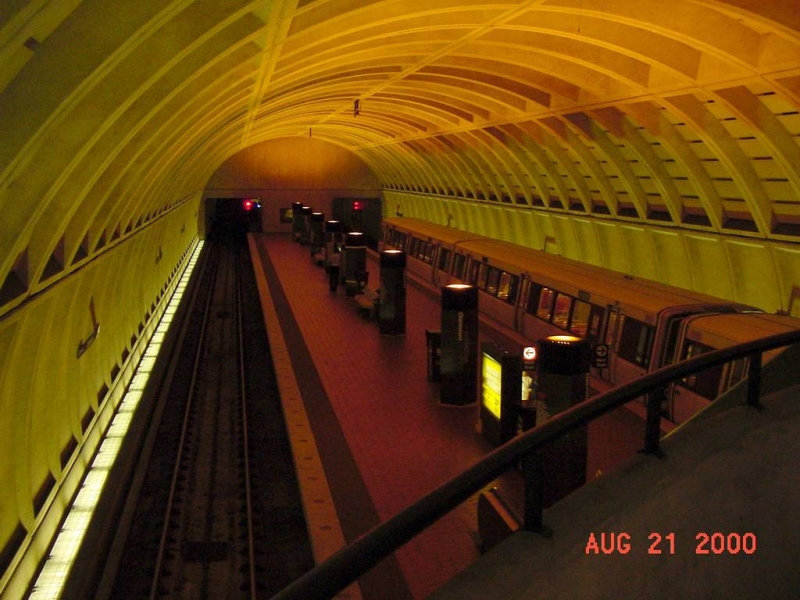
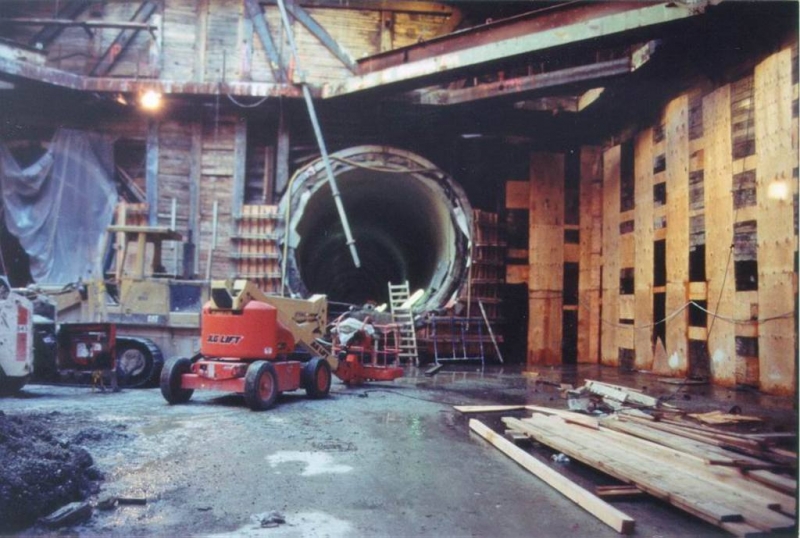
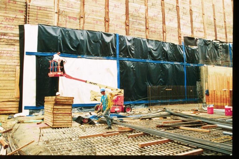
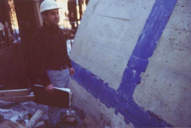
PVC membrane waterproofing system with side drains for Cut & Cover station, including ventilation and service rooms, station entrances and a 600 ft (183 m) long vaulted platform structure. Overall station length: 966 ft (294 m); average depth: 50 ft (15 m), waterproofed area: 180,000 sqft (16700 m²).

Geology description

Stiff to hard brown micaceous silty fine sand, jointed slightly weathered brown hornblende gneiss and jointed quartz.

Description

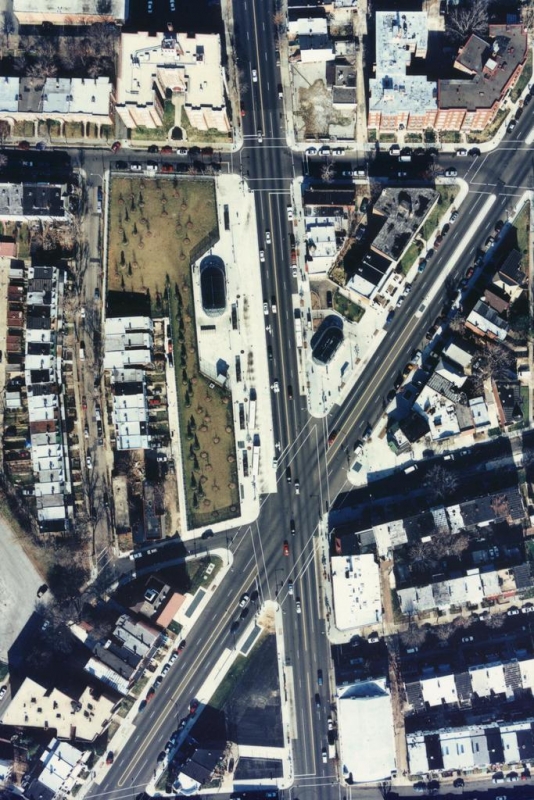
Glenmont, MD is a suburban community located approximately 12 miles north of Washington, DC. The Glenmont Station is located beneath Layhill Road north of Georgia Avenue and features a center paltform and an arch architecture. The Tunnel alignment runs along Georgia Avenue, a busy street flanked by shopping centers and private homes, and connects the Weathon Station with the Glenmont station. Four ground categories and support classes were developed according to the prevalent geology. The contract allowed for changes to the support elements with the engineer's approval and modifications to the ground support categories were made based upon observations of the ground behavior and the initial lining. Monitoring was performed with a variety of instruments (convergence bolts, inclinometers, extensometers, pressures cells, etc). The tunnel waterproofing system is an integral part of the project design and comprises a PVC membrane on a non-woven geotextile over the whole section from side drain to side drain. This system has ensured a dry Tunnel and Station and provided the owner with low maintenance costs.

Categories
Waterproofing
Installation of first Lattice Girder
Inside Station, Portals of Tunnels
Station, Outside, Membrane
Reinforcement, Water Barrier
Completed Station from Mezzanine
Station Overview, Side Waterproofing
Waterproofing Connection at Running Tunnel Portal
Station Wall, Water Barrier
Completed Station from Platform
Steel & Wood Lagging, Side Drainage
Membrane, Water Stop
Change in protection system from rockwool board to PVC membrane
Regular rockwool board protection layer
Waterproofing system with water barrier sectioning
Water barrier pattern
Water barrier embedded into the arched roof
Pouring upper arch supports against installed waterproofing
Installing reinforcement for the invert pour
Single-welding PVC protection membrane onto water barrier
Applying waterproofing onto inbound wall
Longitudinal Section
Typical Station Cross Section
Open-Cut Waterproofing
Formwork on Cut & Cover Station Roof
View of Cut & Cover Station Roof Waterproofing
Finished Running Tunnel Lining
Waterproofing Connection at Running Tunnel Portal
Waterproofing Application on vertical Wall
Waterproofing Details
Welding Waterproofing Membrane and Water Barrier
Completed Station from Mezzanine
Completed Station from Platform

World Trade Center Station - South Boston Piers Transitway

Service Performed
Waterproofing design and supervision
Commencement - Services
December 30, 1996
Completion - Services
October 22, 1998
Location
Boston, MA
United States
Technical data

PVC membrane waterproofing for 150 ft (64 m) of Cut & Cover tunnel, an open cut station and 300 ft (91 m) of boat section. Waterproofing details for over 400 foundation piles and 380 conduit penetrations in groundwater were developed.

Geology description

Silty sand overlaying moderately plastic, organic silt to 18 ft (5.5 m). Below this, layers of uniform fine grey and yellow brown sand and silty sand to a depth of 39 ft (12 m), beneath which is moderately plastic, medium stiff olive grey clay. High water table.

Categories
Waterproofing
Station Profile and Section showing Waterproofing System at Base Slab and Walls
View of Construction Site
Installation of Waterproofing Membrane at Base Slab
Geotextile underlying the PVC Membrane
Welding the Membrane Pieces and fixing the Water Barriers
Installation of Waterproofing System on vertical Walls
Installation of Waterproofing System on Top of Cut & Cover Tunnel

Courthouse Station - South Boston Piers Transitway

Client
Service Performed
Waterproofing Design and Supervision
Estimated cost
$1,800,000
Commencement - Services
December 30, 1997
Completion - Services
December 22, 1998
Location
Boston, MA
United States
Technical data

PVC membrane waterproofing at roof and invert for 460 ft (140 m) of Cut & Cover station with additional polypropylene membrance waterproofing and drainage system at side walls. West of the station 975 ft (297 m) of Cut & Cover tunnel with fully applied PVC membrane waterproofing.

Geology description

Sand and gravel overlaying a moderately plastic, organic silt, which exists to a depth of 24 ft (7 m). Below this, layers of uniform fine brown silty sand and sandy silt to 37 ft (11.2 m). Below this stiff olive grey silty clay. High water table.

Geology types
Categories
Waterproofing

DART - Dallas Area Rapid Transit, Tunnels Inspection

Service Performed
Design and Supervision of Leak Remediation Measures
Location
Dallas, TX
United States
Technical data

Leak remediation measures at the East and West Connector to the Mezzanine Level of City Place Station. Measures consistend of joint and crack grouting, the installation of a felxible membrane lining on the structural concrete lining and a cleaning of the existing drainage system.

Description

Leak remediation measures at the East and West Connector to the Mezzanine Level of City Place Station. Measures consistend of joint and crack grouting, the installation of a felxible membrane lining on the structural concrete lining and a cleaning of the existing drainage system.

Categories
Tunnel Rehabilitation, Waterproofing
Construction methods