Main Menu

You are here

Urban Rail/Bus Stations and Tunnels

Subway Lot 38 - Frankfurt/Main

Service Performed
Technical Consultant for Design, Supervision of Construction and Arbitrator
Commencement - Services
October 01, 1981
Completion - Services
June 01, 1984
Location
Frankfurt/Main , Hesse
Germany
Technical data

2 single track subway tubes, one turning upon the other,length: 2 x 415 m.

Geology description

Frankfurt Clay (clay and sand), waterbearing.

Description

Two single track subway tubes, one durning upon the other, L= 2*415m Monitoring for investigation.

Categories
Urban Rail/Bus Stations and Tunnels

Subway Lot 31b & 31c - Frankfurt/Main

Service Performed
Value Engineering: Design Consultant for a Mined Crossover Section
Commencement - Services
March 01, 1981
Completion - Services
June 01, 1983
Location
Frankfurt/Main , Hesse
Germany
Technical data

2 x 3 single track tubes with corssovers. Excavation section: 40 m² each.

Geology description

Frankfurt Clay (silt and sand), waterbearing.

Description

3 running tunnel each approximately 170 m long

Categories
Urban Rail/Bus Stations and Tunnels
Hole at surface
Hole at surface

Subway Lot 40 - Frankfurt/Main

Service Performed
Technical Consultant for Design, Supervision of Construction and Arbitrator
Commencement - Services
December 01, 1980
Completion - Services
June 01, 1984
Location
Frankfurt/Main , Hesse
Germany
Technical data

Subway, 2 parallel tubes (station and rumming tunnel), L = 2 x 900 m, full section: 35 m² (76 m²), Construction method: NATM.

Geology description

Weathered rock, Frankfurt Clay (clay and sand).

Description

L= 2*900m

Categories
Urban Rail/Bus Stations and Tunnels

Subway Lot 31 - Frankfurt/Main

Service Performed
Value Engineering / Alternative Design
Commencement - Services
July 01, 1980
Completion - Services
June 01, 1984
Location
Frankfurt/Main , Hesse
Germany
Technical data

Three single track tunnels, L = 350 m each.

Geology description

Frankfurt Clay (silt and sand), waterbearing.

Description

Immediate backfill with excavated material at the face. Shotcrete stabilisation at the sink hole (15 cm). Filling of sinkhole with excavated material. Drift trough sink hole with rebar spiling as additional support.

Categories
Urban Rail/Bus Stations and Tunnels

Greenbelt Route Section E8a

Service Performed
Alternative NATM Design and Instrumentation
Estimated cost
$50,000,000
Commencement - Services
April 30, 1985
Completion - Services
May 31, 1993
Location
Washington, DC
United States
Technical data

Two single track running tunnels, L= 6,170 ft (1880m) each, (E Line) 3 Shafts and Cross Adits

Geology description

Clay, sandy clay and sand, parts with some gravel and occasional boulders, decomposed bedrock and weathered bedrock.

Categories
Urban Rail/Bus Stations and Tunnels

Subway Lot 32/S11 - Frankfurt/Main

Service Performed
Supervision of Construction Works and Instrumentation
Commencement - Services
October 01, 1979
Completion - Services
May 01, 1983
Location
Frankfurt/Main , Hesse
Germany
Technical data

Crossover tunnel, L = 2 x 300 m.

Geology description

Frankfurt Clay (silt and sand), waterbearing.

Categories
Urban Rail/Bus Stations and Tunnels
Final cost
$10,000,000

Jubilee Line Extension: Contract 102 - Waterloo and Westminster Station

Service Performed
Value engineering: NATM alternative design at tender stage
Commencement - Services
October 29, 1993
Completion - Services
May 29, 1996
Location
London
United Kingdom
Technical data

New Underground Station: NATM works comprising platform tunnels, central concourse, cross passages, ventilation tunnels etc.

Geology description

Made Ground, Alluvium / Terrace Gravels, London Clay.

Geology types
Categories
Urban Rail/Bus Stations and Tunnels
Final cost
$150,000,000
Lattice Girder, Botom - Detail
Excavation - Crown with Excavator
Excavation with Excavator
Excavation Top Heading Finished
Exavation of Heading (left part) finished
Finsihed Initial Lining
Face support (Bench)
Excavation Bench
Excavation Bench-Invert& Crown
Excavation
Excavation Full Face
General Layout of the NATM Works
Optimized Cross Section with typical Waterproofing and Drainage Details
Overview and Cross Section
Invert Excavation
Shotcrete Application
Sidewall Drift
Reinforcement of the Final Lining
View of Tunnel Junction before Final Lining
Finished Tunnel

Wheaton Station and Tunnels

Client
Service Performed
Design of value engineering; cost proposal for contractor.
Commencement - Services
August 01, 1983
Completion - Services
June 01, 1987
Location
600 5th Street
Washington, DC 20001
United States
Technical data

Subway, 2 tubes, 1 double crossover, 5 shafts and cross adits, 1 station and 1 escalator, Length: 2 x 8530 ft., Construction method: NATM

Geology description

Quartz, diorite, micaschist, gneiss.

Geology types
Description

The project was part of the extension of Glenmont Route north into Maryland and included Wheaton Station and two approx. 2500 m long running tunnels as well as ventilation shafts and a cross-adit. Ilbau America, advised by Dr. Sauer & Partners, recommended changes to the existing conventional design and introduced the New Austrian Tunnelling Method (NATM), which was then used to construct the station tunnels, running tunnels and ancillary structures. The shaft at Hildarose Drive was constructed in conjunction with a large double cross-over.

Categories
Urban Rail/Bus Stations and Tunnels
Final cost
$48,000
Construction methods
Tunnel length
Max:180
Completed station platform
Installing waterproofing
Escalator shaft
Waterproofing installed
Finished Lining
Project number
083D
Final cost
$48,000 USD

DART Segment NC-1B City Place Station

Service Performed
Preliminary design of station including mezzanines, cross adits, ventilation structure; final design with FEM structural computations
Commencement - Services
December 27, 1992
Completion - Services
December 27, 1996
Location
Dallas, TX
United States
Technical data

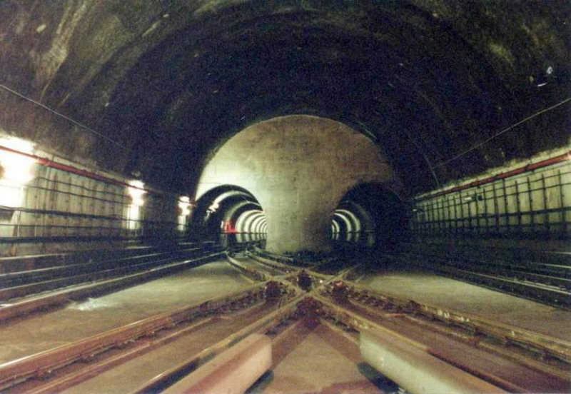
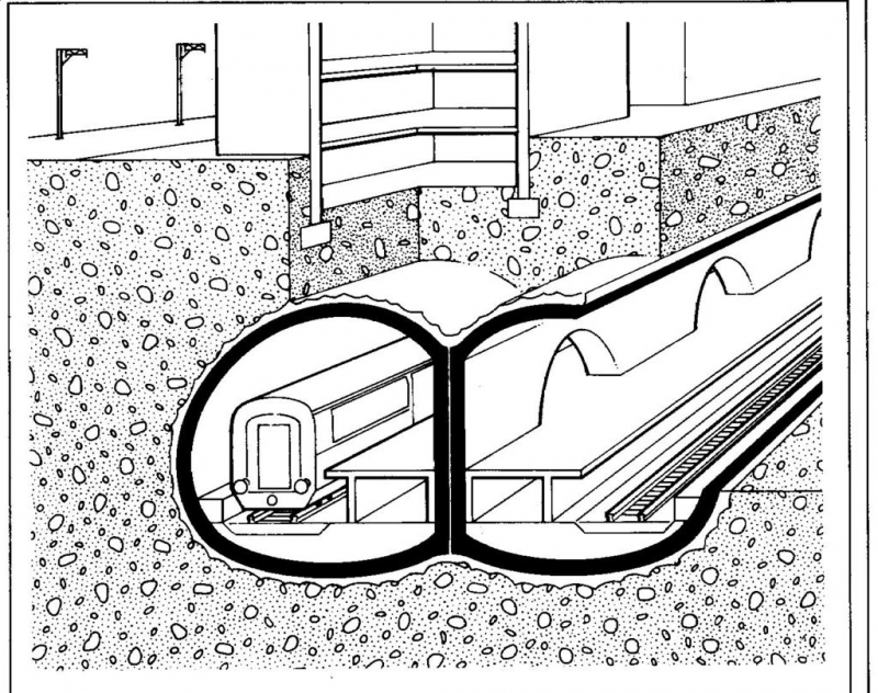
2 single track tunnels, 17.000 ft each, 21 ft Diameter, 2 mined station tubes with multiple passenger and utility cross adits, 3 escalator tunnels, mezzanine, 2 emergency access shafts and connecting tunnels, 4 ventilation structures (tunnels, shafts, chambers).

Geology description

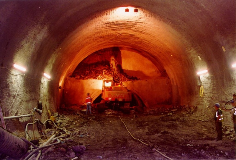
Austin Chalk Formation,Terrace Sands, weathered and unweathered Limestone (Austin Chalk).

Description

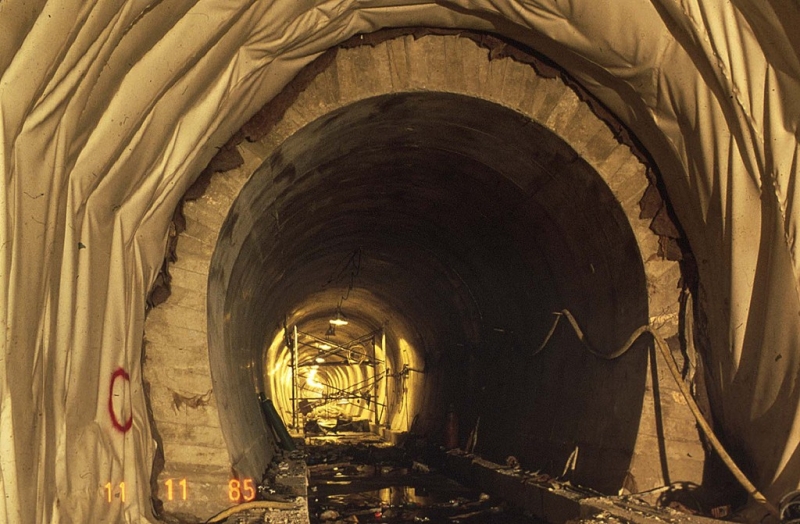
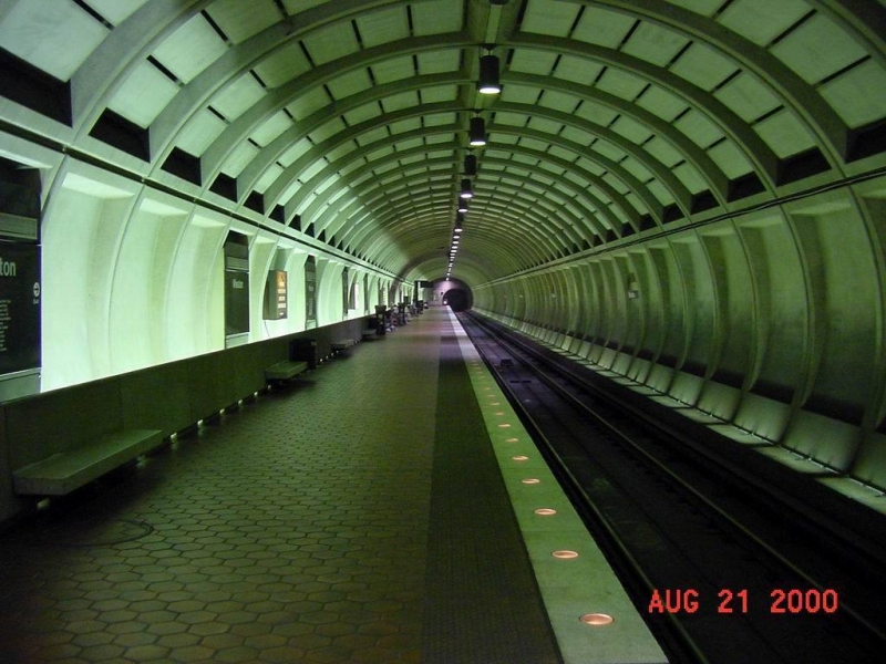
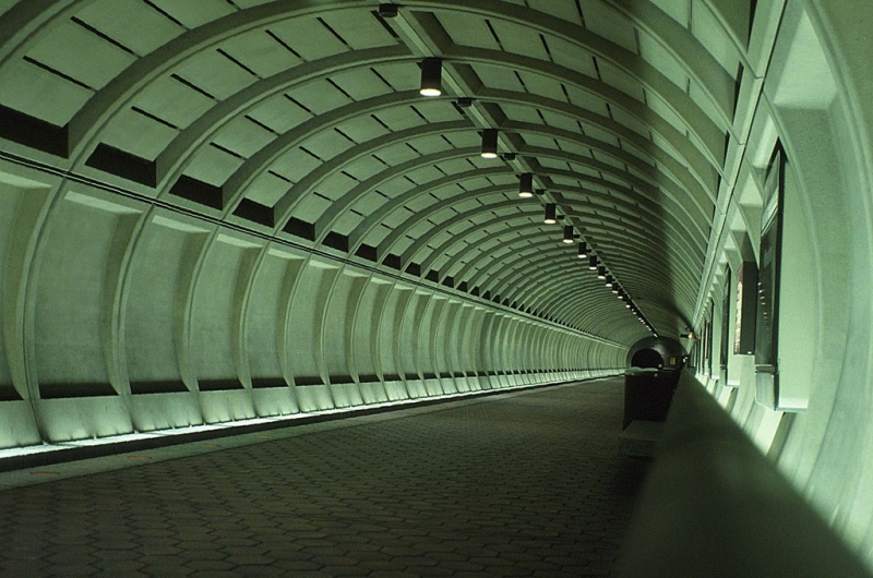
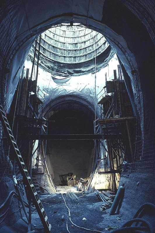
The Dr. G. Sauer Corporation was responsible for the NATM design of the lower escalator, station tunnels, cross adits and emergency access shafts at City Place Station, the only underground station in the Dallas' Light Rail System. Excavation of the station chambers took place 85 ft (26 m) below the road deck of the new North Central Expressway cutting and within 115 ft (35 m) of the adjacent foundations of the multistory City Place tower block. The large 59 ft x 59 ft x 23 ft (18 m x 18 m x 7 m) domed mezzanine level chamber is one of the largest free span caverns constructed in medium soft rock in the US to date. The two station platform tunnels are 79 ft (24 m) apart (centerline to centerline) and involve several cross adits of various sizes with relatively narrow pillars of chalk between. Through a series of comprehensive calculations, the size of openings, excavation sequences, size and advance of headings, the shotcrete and cast-in-place concrete lining requirements were specified.

Categories
Urban Rail/Bus Stations and Tunnels
Final cost
$125,000,000
3D View of CityPlace Station
Cross Section through Station Tunnels, Cross Adit and Escalator Shaft
Cross Adit and Escalator Shaft
Station Enlargement
Shotcrete Robot
Waterproofing of Running Tunnel
Reinforcement and Formwork for Final Lining of Cross Adit
Steel Shutter for Running Tunnel
Final Lining Pour
Finished Running Tunnel
Finished Escalator
Main Drainage
Final Excavation
Initial Lining at the Junction
Raw Tunnel at the Junction
Waterproofing Installation
Final Lining at the Junction
Application of Trowel-Smooth Shotcrete Final Lining
Robotic Application of Fiber Reinforced Shotcrete
Head Wall Final Lining
Junction Final Lining
Cross Adit Final Lining
Junction Final Lining
 Mined portion of southeast entrance and chamber at mezzanine level
Final liner after removal of formwork
Waterproofing in the shaft
Set up of form
Main tunnel drain at cross passage
SW entrance after correction of width and excavation of escalator pit
Inclination of SW entrance prepared for mud slab pour
Cross adit and station tunnel after top heading excavation
Left rib in SE entrance with partial formwork for split pour of arch
Detail of drain pipe penetrating membrane
Clean out detail for drainage system
Formwork for main emergency exit cross adit at intersection with shaft wall
Waterproofing application and rebar installation
Formwork for first pur of walls in main emergency exit shaft chamber
Ventilation tunnel intersection with conduits in invert slab
Wooden forms for trumpet shaped cross adit

DART Segment NC1 - A1/A2

Service Performed
NATM alternative design, FEM design computations for NATM and TBM driven tunnels, ground classification and ground stabilization measures
Commencement - Services
December 28, 1989
Completion - Services
December 28, 1994
Location
Dallas, TX
United States
Technical data

4 single-track light rail tunnels, total length 11,500 ft (3505 m).

Geology description

Shale, clay, terrace sands and gravels (below groundwater level). Weathered and unweathered Limestone (Austin Chalk).

Geology types
Categories
Urban Rail/Bus Stations and Tunnels
Final cost
$50,000,000
Escalator Shaft
Twin Portal
Assembly of Robbins TBM
TBM before Start of Excavation
TBM Breakthrough
Shotcrete Application
Finished Tunnel
Shotcreting robot
TBM assembled
Road Header

Pages