Main Menu

You are here

Urban Rail/Bus Stations and Tunnels

Metro de Santiago, Linea 2 South Extension, Lo Ovalle to La Cisterna

Owner
Service Performed
NATM design support services and on-site monitoring.
Commencement - Services
January 30, 2001
Completion - Services
December 30, 2004
Location
Av. Libertador Bernardo O'Higgins 1414
Santiago
Chile
Technical data

2.5 km Dual Track Running Tunnels and two Stations with a maximum span of 16.2 m. Excavation of 60-65 m² running tunnel in combined top heading/bench with a subsequent invert excavation. Reinforcement consists of lattice griders and welded wire fabric for initial lining and welded wire fabric for final shotcrete lining.

Geology description

Ripio de Santiago (quaternary conglomerate) consists of a stable matrix of smooth rounded rocks held by bonding fines. Due to earthquake activity it gained compaction and interlocking.

Geology types
Description

The Santiago Metro network comprises five lines. The Linea 2 South extension included 2.5km dual track running tunnels and two stations with a maximum span of 16.2m. Further, an excavation of 60-65m2 running tunnel in combined top heading/bench with a subsequent invert excavation. Reinforcement consisted of lattice girders, welded wire fabric for initial lining and welded wire fabric for final shotcrete lining. Dr. Sauer and Partners assisted in the production of design criteria for the final design and produced finite element structural computations for the large station caverns.

Activity
Categories
Urban Rail/Bus Stations and Tunnels
Final cost
$29,600,000
Construction methods
Excavations of topheading
Shaft and portal
Side drifts, Junction station running tunnel
First side drift
Installation of lattice girder and wire mesh
Headwall
Start-up of sidewall drift
Kurt Egger
Reinforcement of headwall
Compact sand and gravel
Support beam
El Parron South
El Parron South
Sidewall drift
Face support earth wedge located in the top heading
Stress meter
Stress meter
Gerstgrasser Otto
Gerstgrasser Otto
Brunner W.
Dr.Sauer & Gerstgrasser Otto
FEM-Model of Access Tunnel - Station Tunnel Junction
Sidewall Drift Portal
Shotcrete Application
Breakout from Tunnel
Excavation of Center Drift
Demolition of Temporary Sidewall
Mucking out through Access Shaft
Linea 5 - Junction Station-Tunnel
Installation of Tracks
Completion of Electrical Installations in Station
Linea 5 - Finished Station
Excavation of invert
Project number
296E
Final cost
$29.6 million USD

Central Section, Sec. 5.2.

Service Performed
Independent Design Check including Tunnel Excavation, Primary and Final Linings and M&E Specification.
Commencement - Services
June 01, 1999
Location
Thessaloniki
Greece
Technical data

A modern closed motorway 680 km long following an alignment running across Epirus and Northern Greece from Lgoumenitsa to Evros. DSC provided design review services on three twin bore two lane highway tunnels, total length 1.26km (each bore), cross section 106m2 approx. Tunnel supported by rock bolts and shotcrete with inner reinforced concrete lining. Design check included seismic and explosion loading cases.

Geology description

Tunnel 1: phyllites inter-changed layers and lenses of bedded crystal limestone (marble), sandstone. Tunnel 2: slightly to moderately weathered sandstone. Tunnel 3: marble, crystal limestone (carbonates), mica shist and gneiss (mica gneiss).

Categories
Urban Rail/Bus Stations and Tunnels

Beacon Hill Station

Service Performed
NATM / SEM station design and construction supervision.
Estimated cost
$250,000,000
Commencement - Services
February 26, 2000
Completion - Services
December 28, 2007
Location
401 S. Jackson Street
Seattle, WA 98104
United States
Technical data

NATM Light Rail Station located 150 ft (46 m) beneath surface. Station complex includes central elevator/access shaft, concourse, opposing platform tunnels and cross passages. Platform Tunnel Section: 36 ft w x 31 ft h; Platform Tunnel Area: 925 sqft (86 m²); total Station Excavation Area: 63,000 sqft (5853 m²).

Geology description

Over-consolidated glacial clay and till with fracutured zones. Intermittent sand and silt layers with perched groundwater.

Geology types
Description

The Beacon Hill Tunnels and Station are part of the 22.5km initial segment of the Sound Transit Central Link Light Rail Line that will establish a high capacity commuter connection from downtown Seattle to Tacoma. The 1300m running tunnel under Beacon Hill will be mined by Earth Pressure Balance Machine (EPB), while the deep mined Station will be constructed using slurry walls and the New Austrian Tunneling Method (NATM), referred to as Sequential Excavation Method (SEM) for this project.

Activity
Categories
Urban Rail/Bus Stations and Tunnels
Bid cost
$280,000,000
Final cost
$280,000,000
Construction methods
Tunneling under
Max Overburden
Min:120 Max:140
Beacon Hill Station layout
Tunnel excavation under way
3D rendering of Beacon Hill Station complex
Platform tunnel cross section
Schwind Thomas
Installation of Vacuum Dewatering
Rendering of Beacon Hill Station
Project number
325
Final cost
$280 million USD

East London Line - Thames Tunnel Refurbishment

Service Performed
Design of the tunnel refurbishment works including the waterproofing and drainage, the new tunnel lining and track slab, and the new track alignment. Construction supervision.
Commencement - Services
November 01, 1995
Completion - Services
January 01, 1997
Location
Rotherhithe, London
United Kingdom
Technical data

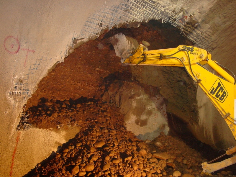
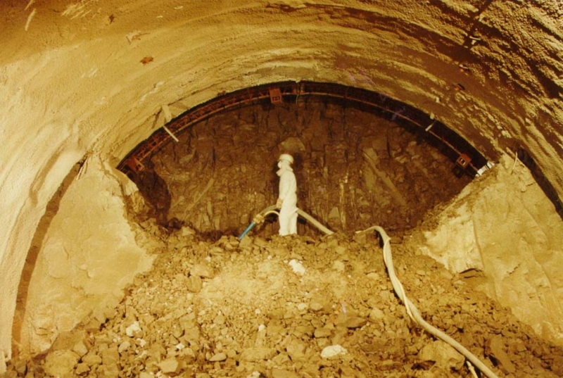
The brick lined tunnel constructed by Mark Brunel between 1825 and 1841 was the first to be bored underwater using a shield and comprised of a twin arch tunnel, 375m in length, with cross passages every 5.5m. The new lining has been designed to minimizethe removal of existing structural brickwork and has a similar shape with cross passages to match the original tunnel. The reinforced concrete/shotcrete lining includes steel fibers to increase the strength and durability of the lining. A waterproof membrane has been installed around both tunnels and the cross passages between the structural brickwork and the new concrete lining.

Categories
Urban Rail/Bus Stations and Tunnels

London Bridge Jubilee Line Extension

Service Performed
Detailed temporary and permanent lining design, settlement assessment and construction supervision.
Commencement - Services
November 01, 1994
Completion - Services
June 29, 1997
Location
21 Duke Street Hill
London
United Kingdom
SE1 2SW
United Kingdom
Technical data

Temporary shotcrete lining design of running tunnels, step plate junction, temporary works access tunnels, shafts, platform and concourse tunnels and ventilation tunnels. Permanent lining design, reinforced concrete and steel fibre reinforced shotcrete.

Geology description

Made ground, alluvium / terrace gravels, London Clay, Woolwich & Reading Beds.

Geology types
Description

London Bridge is a major new station on the 16km long Jubilee extension of London Underground. The vicinity of construction is considered highly sensitive due to old existing tunnels and surface structures. The original design called for hand mining, shield machines for excavation and a segmental cast iron lining for tunnel support. NATM handled the geometrically complicated tunnel alignments and shapes with significantly lower effort. It minimised settlements, which reduced the amount of compensation grouting estimated.

Activity
Categories
Urban Rail/Bus Stations and Tunnels
Final cost
$120,000,000
Complex underground station arrangement
Excavation of tunnel junction
Cross Sections
Geology
Bottom of the Access Shaft
Step Plate Junction
Construction of Intersection
Finished Reinforced Concrete Lining
Project number
183E
Final cost
£120 million GBP

North Shore Connector

Service Performed
Alternative NATM tunnel design, cost estimate & finite element analysis.
Commencement - Services
July 01, 2002
Completion - Services
January 01, 2008
Location
Alpha Dr, Harmar Township
Pittsburgh, PA 15238
United States
Technical data

NATM running tunnel connecting Convention Center station with surface to be constructed beneath historic downtown structures as part of existing LRT system expansion. Provided initial design package, including detailed cost estimate. Tunnel Length: ~446'* Cross Section: 41'-4" x 26'-11"; 895.24 ft^3 *Including widening zone for track cross-over.

Geology description

Fill, alluvium (granular and cohesive), fluvioglacial deposits and bedrock.

Geology types
Description

The North Shore Connector Project consisted of three underground station structures and running tunnels, excavated with TBM and Cut-and-Cover tunneling methods. It also included a twin bore tunnel under the Allegheny River. Dr. Sauer and Partners provided design review and design support services. The development of the waterproofing system for underground structures including tying into an existing station using a flexible membrane system, combined with a sectioning system that allows for section grouting instead of the entire structure if a leak is detected was also provided.

Activity
Categories
Urban Rail/Bus Stations and Tunnels
Final cost
$7,600,000
Construction methods
Project overview
Cut-and-Cover method
Project number
361D
Final cost
$7.6 million USD

Shepherd's Bush Station - MIP

Service Performed
Feasibility Study looking at ways of providing Congestion Relief and MIP lift access from surface to platform level, provision of tunnel and underground space design.
Estimated cost
$100,000
Commencement - Services
March 24, 2003
Location
London
United Kingdom
Technical data

Limited surface access and highly congested underground space with old cast iron tunnels platform tunnel very close together with passenger access and exit at the western end only. The feasibility design looked at options to improve the passenger space at the existing access and exit point, provide a second means of escape, MIP lift access to the surface and smoke extraction.

Geology description

Made Ground/Terrace Gravels overlying London Clay to depth. Groundwater approx 3m bgl. Limited clay cover above crown of tunnels.

Categories
Shaft, Urban Rail/Bus Stations and Tunnels

3rd Street Light Rail Project - Chinatown Station

Service Performed
Tunneling Sub-Consultant on NATM Subway station design
Estimated cost
$763,800,000
Commencement - Services
January 01, 2002
Completion - Services
October 22, 2003
Location
San Francisco, CA
United States
Technical data

Conceptual and preliminary engineering services for the Chinatown Station of the MUNI Light Rail System in San Francisco. The responsibilities include constructability evaluations, alignment and construction alternatives studies and preparation of preliminary design documents. Alternatives, including deep bored tunnel vs. shallow NATM tunneling will be evaluated.

Geology description

Rugged bedrock hills consisting of highly deformed fractured rock of the Franciscan formation, overlain by sedimentary marine deposits (Colma Sands), fluvial deposits (Alluvium) and artificial fill. Very dense sands, inter-fingering of moderately plastic stiff silty clay.

Categories
Urban Rail/Bus Stations and Tunnels
Construction methods

Heathrow Express Rail Link

Service Performed
Tender design, detailed design and construction supervision.
Commencement - Services
April 01, 1990
Completion - Services
December 27, 1992
Location
Nelson Road
London
TW6 2GW
United Kingdom
Technical data

Railway link between Heathrow Airport and Paddington Station 2 underground stations: (Central Terminal and Terminal 4). Trial station tunnel with three different excavation and support sequences; lenght: 100 m, diameter: 8 m approx.

Geology description

Soft ground, terrace gravels overlying London Clay.

Geology types
Description

The Heathrow Express Link provides a 15 minute high speed rail service between Paddington Station and Heathrow Airport. A 7.25 km spur running for the most part in tunnel provides the airport with underground stations at the Central Terminal area (Terminals 1, 2 & 3) and Terminal 4. Provision was also made for a link to the at this point proposed Terminal 5. The 5.5 km long tunnelled section will pass under the M4 motorway with the portal located to the north.

Activity
Categories
Airport Tunnel, Urban Rail/Bus Stations and Tunnels
Final cost
$2,200,000
Removal of temporary side wall
Shotcrete lining completed
Finished adit
Subway entry at surface
Lattice girder and wire mesh installed at invert
Excavation of bench completed
Excavation of the side drift
Invert,installed lattice girder and wire mesh
Installed pressure cells
Installation of L.G. in top heading of side drift
Proposed Excavation Sequences
Instrumentation Scheme
Finite-Element Calculation
Excavation Sequence Type 1
Excavation Sequence Type 2
Excavation Sequence Type 3
Completed Trial Tunnel
Finished Platform Heathrow Central Terminal
Concourse Tunnel
Completed Escalator Shaft
Project number
172D
Final cost
£2.2 million GBP

Pages