Main Menu

You are here

Site Supervision & CM, QA/QC

New Studley Water Tunnel

Service Performed
NATM design, construction supervision and instrumentation
Commencement - Services
January 29, 1988
Completion - Services
December 29, 1990
Location
Birmingham
United Kingdom
Technical data

Large diameter shaft constructed using NATM for the diversion of a Water Supply Tunnel.

Geology description

Sandstone, Shale / Marl, Limestone

Geology Type: Hard Rock

Geology types
Categories
Final cost
$25,000,000
Service areas
Site Supervision & CM, QA/QC, Tunnel Design & Specialities
Shotcreting
Overview drawing
Overhead View of Shaft and Water Tunnel
British Construction Award 1989

B 27 Bypass Tunnel Oberrieden

Service Performed
Detailed design, instrumentation and construction supervision
Commencement - Services
December 28, 1990
Completion - Services
December 28, 1992
Location
Bad Sooden-Allendorf
37242 Oberrieden, Hesse
Germany
Technical data

Two lane road tunnel, 520 m length, construction techniques incl.: NATM, Doorframe Slab Method, Cut & Cover, Barrel Vault Method under existing railway embankment.

Geology description

Bunter Sandstone (sandstone, clystone), sand, clay and 120 year old railway embankment (rock fill, sand, clay, gravel).

Geology Types: Mixed Face

Description

The German Federal Railway Authority imposed high demands on safety since it did not allow for any disruption to railway traffic.

Barrel Vault Method, Doorframe Slab Method

Activity
Final cost
$12,500,000
Service areas
Site Supervision & CM, QA/QC
Special Construction techniques
Canopy, start of shotcrete work
Canopy, anchor beam
Installation of the Barrel Vault
Portel under construction, barrel vault completed
Doorframe slap, I-beam installation
Installation of the barrel vault
Top heading
Sidewall drift, top heading, grouting of foundation aera
Sidewall drift, grouting at invert & bench
Sidewall Dirft, Bench
Side Drift Top Heading, Break Through
Cross Section, Excavation Sequences
Side Wall Drift, Temporary Shotcrete Invert at Top Heading
Sidedrift, Top Heading, Shotcreting
Installation of the Barrel Vault, Drill
Sketch of Railway Underpass
Finished Portal
Grouting at Invert and Bench
Installed Barrel Vault
Door Frame Slab, Open Cut for Slab Preparation
Portal Preperation
Pipes isntalled
Pipes installation at T.H.
Pipes installation at T.H
Installed barrel vault
History
Barrel Vault pipe/whole through
Test
Installed
Pump utilities
Installation of Pipes
Cement for grouting
Installation of pipes
Equipment Drill Rig
Drill device
Installation of pipes
In_Situ test
Project Overview and different Construction Methods
Excavation and Support Concept
Scheme of the Doorframe Slab Method
Doorframe Slab Method
Scheme of the Barrel Vault Method
Barrel Vault at S-Portal
Barrel Vault at N-Portal
Barrel Vault Pipe Installation
Shotcrete Canopy at S-Portal
Tunnel Portal beneath Active Rail Line
Shotcrete Middlewall
Finished Tunnel

Subway Lot 32/S11 - Frankfurt/Main

Service Performed
Supervision of Construction Works and Instrumentation
Commencement - Services
October 01, 1979
Completion - Services
May 01, 1983
Location
Frankfurt/Main , Hesse
Germany
Technical data

Crossover tunnel, L = 2 x 300 m.

Geology description

Frankfurt Clay (silt and sand), waterbearing.

Final cost
$10,000,000
Service areas
Site Supervision & CM, QA/QC

Jubilee Line Extension: Contract 102 - Waterloo and Westminster Station

Service Performed
Value engineering: NATM alternative design at tender stage
Commencement - Services
October 29, 1993
Completion - Services
May 29, 1996
Location
London
United Kingdom
Technical data

New Underground Station: NATM works comprising platform tunnels, central concourse, cross passages, ventilation tunnels etc.

Geology description

Made Ground, Alluvium / Terrace Gravels, London Clay.

Geology types
Final cost
$150,000,000
Service areas
Site Supervision & CM, QA/QC, Tunnel Design & Specialities
Lattice Girder, Botom - Detail
Excavation - Crown with Excavator
Excavation with Excavator
Excavation Top Heading Finished
Exavation of Heading (left part) finished
Finsihed Initial Lining
Face support (Bench)
Excavation Bench
Excavation Bench-Invert& Crown
Excavation
Excavation Full Face
General Layout of the NATM Works
Optimized Cross Section with typical Waterproofing and Drainage Details
Overview and Cross Section
Invert Excavation
Shotcrete Application
Sidewall Drift
Reinforcement of the Final Lining
View of Tunnel Junction before Final Lining
Finished Tunnel

East London Line - Brunel Thames Tunnel Refurbishment

Service Performed
Design of tunnel refurbishment including waterproofing; construction supervision
Commencement - Services
August 27, 1995
Completion - Services
October 19, 1997
Location
30 The South Colonnade
London
E14 5E4
United Kingdom
Technical data

Twin arch tunnel, 375 m (1230 ft) in length, with cross passages every 5.5 m (18 ft).

Geology description

The tunnel is covered by the Thames river bed sediments, water saturated silt, clay and sand or a suspension thereof and even partially exposed to the river water.

Description

The brick lined tunnel constructed by Mark Brunel between 1825 and 1841 was the first to be bored underwater using a shield and comprised a twin arch tunnel, 375m in length, with cross passages every 5.5m. The new lining has been designed to minimise the removal of existing structural brickwork and has a similar shape with cross passages to match the original tunnel. The reinforced concrete/shotcrete lining includes steel fibres to increase the strength and durability of the lining. A waterproof membrane has been installed around both tunnels and the cross passages between the structural brickwork and the new concrete lining.

Activity
Final cost
$21,000,000
Service areas
Rehabilitation & Tunnel Widening, Site Supervision & CM, QA/QC
Tunnel after Rehabilitation
Formwork and waterproofing
Old Engraving
Cross Section of refurbished Tunnel (left), original Tunnel (right)
Tunnel Portal during Construction
Partially completed Tunnel showing the structural Brick Masonry
Completed Tunnel and Cross Passage Linings prior to Installation of the Services and Track Works
Early Construction Stage - Installation of the Tunnel Invert Waterproofing System
Installation of the Tunnel Invert and Track Slab Reinforcement
Preparing Tunnel Roof for Waterproofing System
Steel Archs Tunnel Support
Final Cast-in-Place Lining Process
Before Rehabilitation - Cross Passages with the architecutal Features partially eroded away
Partially finished Final Lining
After Rehabilitation - The architectural Features shown were cast-in-place as Part of the Tunnel Final Lining
Reinforcement and Waterproofing at the Invert
Tunnel before Rehabilitation
Cross Passage before Rehabilitation
Cross Section
Inner Lining and Water Proofing
Project number
233
Final cost
£21 million GBP

Southport Deep Shaft

Service Performed
NATM design and construction supervision
Location
Southport
United Kingdom
Technical data

9 m (29.5 ft) excavated dia. 80 m (262 ft) deep vertical shaft for sewage treatment. Upper 28 m (92 ft) of shaft excavation supported using diaphragm walls with the remaining 52 m (170 ft) excavated using NATM with a reinforced shotcrete primary lining. Permanent lining comprises slipformed reinforced concrete.

Geology description

Beach Sand overlying Mercia Mudstone overlying Halite (rock salt).

Geology types
Categories
Service areas
Site Supervision & CM, QA/QC, Tunnel Design & Specialities
Sahft wall, support elements
Plan View
Cross Section
Overhead View showing Shaft
View from the Shaft Base
Work at Shaft Base
Reinforcement before Shotcrete Lining Installation
Shaft at the Surface
One Round of Shaft Excavation Completed
Crane at Shaft Surface

Ortsumfahrung B311

Service Performed
General Consultant for Design and Construction
Estimated cost
$21,000,000
Commencement - Services
March 22, 1994
Completion - Services
December 01, 1994
Location
Kirchham, Salzburg
Austria
Technical data

New Two Lane Roadway Tunnel constructed using NATM and Doorframe Slab Method, included 300m (900 ft) of approach ramps. Dimensions: Height 10.30m (~34’ ft) x Width 11.50m (~38 ft) Length: 700m (2,229 ft) Section: ~94m2 (1,033 ft2) Roadway Overburden: 5.15m (~17 ft)

Geology description

Sandstone

Service areas
Site Supervision & CM, QA/QC, Tunnel Design & Specialities

Berry Street Tunnel

Client
Service Performed
Value engineering design and construction supervision
Commencement - Services
September 27, 1996
Completion - Services
December 28, 1997
Location
Pittsburgh, PA
United States
Technical data

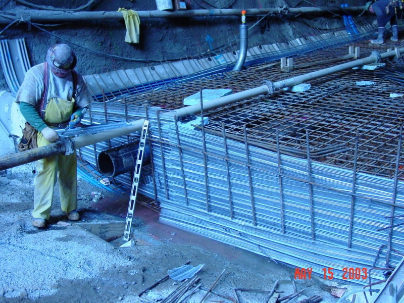
Enlargement of a 2,800 ft (853 m) long, two laned brick lined tunnel to a 34 ft (10 m) wide horseshoe shaped tunnel with approx. 150 ft (46 m) of overburden. Primary lining: steel fibre reinforced shotcrete and lattice girders. Waterproof membrane with an unreinforced concrete secondary lining.

Geology description

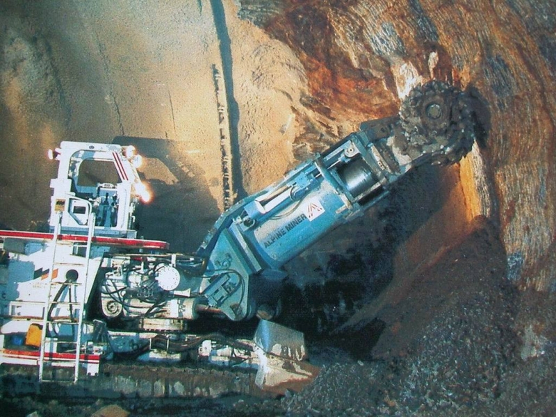
Medium hard to soft sandstone and shale with thin beds of coal and claystone, non-cohesive fill of the original cut and cover section.

Geology types
Description

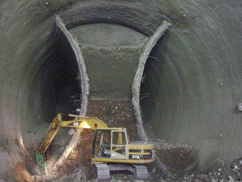
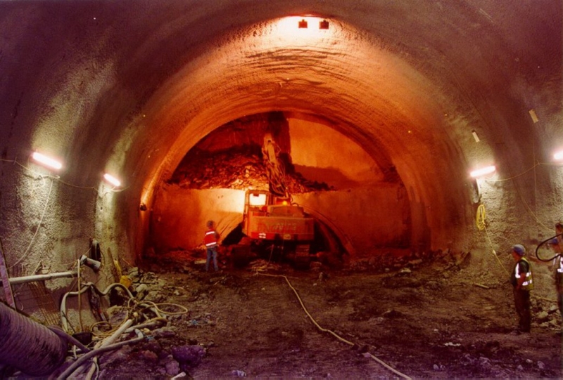
The original tunnel was built in 1865 as a 12 ft wide (4 m) single-track rail tunnel. It was widened in 1873 to 25 ft (8 m) double-track with a 26 in-thick (66 cm), brick-lined horseshoe design. After several structural repairs, mainly for spalling bricks, it was finally closed in the early 1960s. More than 30 years later the Port Authority of Allegheny County saw benefits in adapting the former railroad alignment and right of way to its new bus way connection between downtown Pittsburgh and the new Pittsburgh International Airport. A NATM value engineered proposal in the tunnel refurbishment contract provided US $ 2 mil cost savings compared to the original bid. The redesign was based on elevating the tunnel alignment so that the future tunnel crown could be excavated in better ground conditions and on changing the proposed horseshoe to a "rounded" cross section. This combined with the utilization of the NATM allowed a 40 % reduction in shotcrete thickness, a 22 % reduction in concrete lining thickness and the elimination of the reinforcement in the final lining. Furthermore, the NATM proposal eliminated pre-excavation grouting (200,000 bags of cement) and over 10,000 rock bolts while reducing lining thickness. During tunneling up to three headings were excavated simultaneously, one from each portal and one started within the tunnel, averaging a total excavation progress of 15.4 ft (4.7 m) /24h day. Following waterproofing, the concrete lining was completed 16 month after beginning of the reconstruction.

Final cost
$18,000,000
Service areas
Cross and Longitudinal Section
Cross Section
Southwest Portal before Rehabilitation
Hydraulic Ram removing existing Brick Lining
Voids in Tunnel Crown
Shotcrete Application after removing Bricks
Waterproofing System installed
View of the Shotcrete Canopy Section
Final Lining Shutter
Completed Southwest Portal
Lattice girder erection
Shotcreting of Canopy
Waterproofing Completed
Formwork and Carrier
Dwg./ Cross Section and Longitudinal Section
Removal of the Existing Brick Lining
Southwest Portal Completed
Rebar Spiling at Crown
Instalation of Rockbolts
Cross Section, Geology, Overbreak
Cross Section, Overbreak
SFR Shotcrete, Rock Dowels
Canopy,Lattice Girders, Shotcreting
Final Lining, Cast in Place

MBTA, Russia Wharf Segment, Section CC03A

Service Performed
NATM detailed design and site supervision during construction.
Commencement - Services
December 28, 1996
Completion - Services
December 19, 2004
Location
Boston
Boston, MD 02101
United States
Technical data

Road tunnel with 2 lanes and a lenght of 400 ft. Study into the construction of either a single tunnel or a binocular tunnel with central pier using the shotcrete support method with ground freezing pre-support to protect overlying historic building.

Geology description

Made ground, peat, glacial till (cohesive, plastic). The peat horizon undulates along the route, in places it is expected to be exposed in the top half of the proposed tunnel face.

Geology types
Description

The Russia Wharf segment is the last, but most challenging section of the Silverline Phase II construction for the Massachusetts Bay Transportation Authority (MBTA). The line is designed to provide a dualmode bus rapid transit connection between the central business district in South Boston to the new Convention Center. The tunnel passes diagonally under the 100 year old Russia Wharf complex, which comprises three seven-story buildings with steel frames and brick facades listed in the National Register of Historic Places. The chosen construction method was NATM in conjunction with ground freezing, for the first time in the US. Steel fibre reinforced concrete was used for temporary and permanent lining.


Final cost
$18,000,000
Construction methods
Special Construction techniques
Tunneling under
Groundwater control
 Overview of West Cofferdam
Sheet Pile Wall
Excavation of T.H. first round
Reflectors for the monitoring
4 Bar L.G.
Short tunneling
Steel pile for underpinning
Close up of L.G.
Convergence Bolt before schotcreting
4 Bar longitudinal L.G.
Shotcrete at the face of T.H. & Bench
Installation of spiles
Spiles installed
Spiles installed
Wood piles
Installation of Spiles
Excavation of Invert
 Pile Shoe Reinforcement in T.H.
L.G & Wire Mesh installed
Butt plate connection
L.G & Wire mesh, Wood piles,Pile for underpinning
Wood files
Shotcreting, Pile for Underpinning
Overview of west Cofferdam
Overview of "Russia Wharf Building"
L.G & Wire Mesh, Pile for underpinning
L.G. installation
Pile Shoe reinforcement in T.H
View of tunnel and Graphic Arts Building
L.G. & Wire Mesh at Portal Area
Wood Piles, Pile for Underpinning
Compressible Pad onto wood piles
Wood piles, piles for underpinning
Profiling in T.H using Roadheader
View of "Russia Wharf Buildings"
Wood piles, Piles for underpinning
Shotcreting
Waterproofing at Invert, Water Barriers
Installed Waterproofing, Formwork for Center Wall
Installation of Rebar Spile
L.G & Wire Mesh installed, Shotcrete Invert in T.H.
Overview Tunnel Inside
L.G. & Wire Mesh, Piles for Undpinning
L.G. & Wire Mesh, Halfenbox
Shotcrete Tunnel completed
Grouting of Spiles completed
Waterproofing installed at Invert, Halfenbox
Reinforcement of center wall
Reinforcement of a Blockout in the center wall
Pouring concrete of Invert
Invert
Welding operation
Control & Grouting Pipe, Reinjectable Hose
Control & Grouting Pipe, Fuco Hose
Top of Centerwall
Reinforcement of Shotcrete
Installation of L.G. 1st round
Excavation of 2nd half of Binocular T.
Shotcrete F.L., Center wall
Binocular Tunnel
Installation of spiles
Freezing Pipes
Freezing Pipes
1st half of binocular T.
Pile shoe reinforcement in T.H.
Plan View of the Binocular Tunnel
Tower Crane View
Tower Crane View of Russia Wharf Complex
Longitudinal Section for the Binocular Tunnel
Binocular Tunnel Section
Ground Freezing Tubes and Settlement Compensation under Russia Wharf
Top Heading Excavation cutting old wooden support piles
Reinforcing and Encasing cutted wooden Piles
Reinforcement of Middlewall of Binocular Tunnel
Excavation of the second Tube of the Binocular Tunnel
Waterproofing of the Binocular Tunnel
Freezing Pipes at surface
Shoe reinforcementon timber piles
Project number
263D
Final cost
$18 million USD

Bergen Tunnel Rehabilitation

Client
Service Performed
Geotechnical investigation, structural computations, preliminary rehabilitation design and supervision of rehabilitation works.
Estimated cost
$56,000,000
Commencement - Services
May 25, 2001
Completion - Services
October 17, 2002
Location
Jersey City
Jersey City, NJ 07304
United States
Technical data

Widening of a 4,300 ft (1310 m) long, 25 ft (7.6 m) wide double track, partially brick-lined railway tunnel built in the late 1800s. Excavation and support according to the principles of NATM with two support types. Flexible membrane waterproofing and cast in place final lining.

Geology description

Moderately close to closely jointed and fractured diabase; light gray to dark gray, very hard with moderate water infiltration.

Description

The Bergen Tunnel on the New Jersey Transit network is a double track, horseshoe shaped rail tunnel, built in the 1870s, passing through fractured diabase. Over time, water ingress has caused operational problems. In 2000 the owner decided to undertake major structural rehabilitation. The brick lining was stripped out and the original profile was enlarged to take a new reinforced in-situ concrete lining and drainage system. Old ventilation shafts were backfilled. Two large openings were retained for tunnel ventilation, emergency access and to house new power and electrical substations.

Activity
Final cost
$56,000,000
Service areas
Installation of membrane waterproofing system
Rehabilitated tunnel with final cast-in-place lining
Before Rehabilitation - East Tunnel
Portal Slope Stabilization
Typical Cross Section
Results of initial Blast to remove Brick Lining
Void Reinforcement
Shotcrete Robot
Final Lining Form and exposed Waterproofing System
Vent
Lettice Shotcrete
Existing bricklining
Before shotcreting
Side drain
Unsupported rock portal
Shotcrete portal
Shotcrete lining
Unsupported Tunnel wall
shotcreting
complete shotcreting
Complete shotcrete
Installtion of spiles
Spiling
Footing
complete installation
Sidedraine
Project number
265
Final cost
$56 million USD

Pages