Service Performed Conceptual, preliminary, detailed design of underground caverns, egress tunnels and mined shafts; scheduling and cost estimating; risk management; specifications and tender. Onsite support during construction.
Geology description
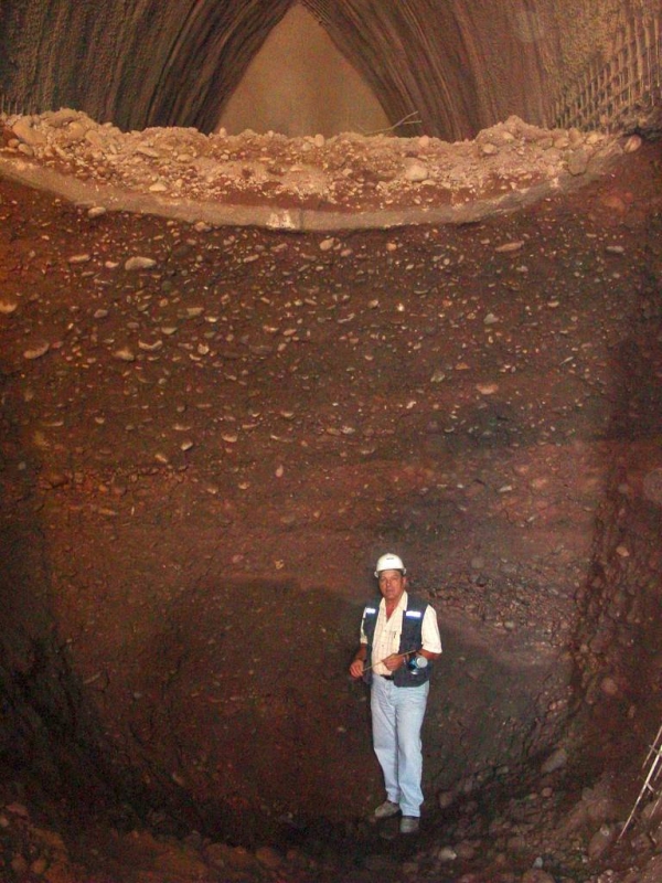
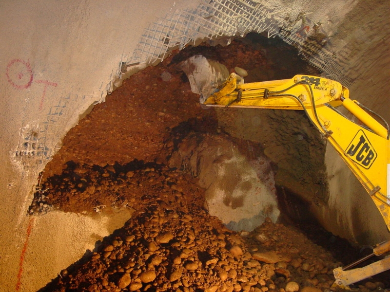
The geology ranges from soft clay (Bay Clay) to stiff sands (Colma Sands) and competent to highly fractured rock (Franciscan Formation). The groundwater table is generally above the cavern springline.
Description
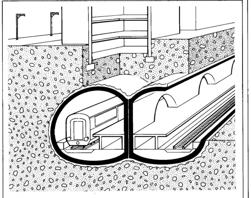
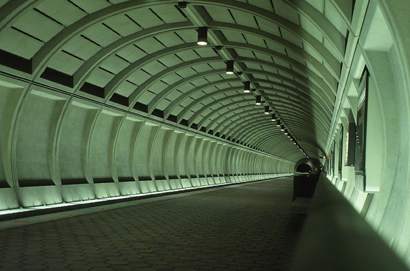
Chinatown Station is the Northern Terminus of the Third Street Light Rail Project, which is located in a dense urban neighbourhood, underneath a busy street and directly adjacent to numerous old buildings, as well as one high-rise building. The station encompasses a Cut-and-Cover headhouse for passenger entry, three large station caverns and an emergency egress shaft. In order to minimise excavation volume and optimise cost and schedule, the ventilation ducts are located below the platform level, and routed into the headhouse.


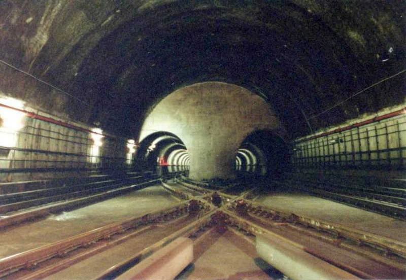
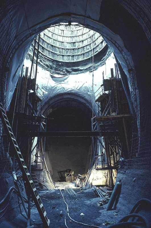
, CP1-CH1 connection adit (centre) and PL2RC (right)")


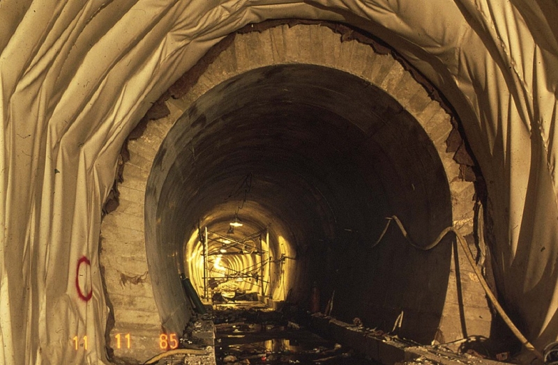
")