Main Menu

You are here

Design

Beacon Hill Station

Service Performed
NATM / SEM station design and construction supervision.
Estimated cost
$250,000,000
Commencement - Services
February 26, 2000
Completion - Services
December 28, 2007
Location
401 S. Jackson Street
Seattle, WA 98104
United States
Technical data

NATM Light Rail Station located 150 ft (46 m) beneath surface. Station complex includes central elevator/access shaft, concourse, opposing platform tunnels and cross passages. Platform Tunnel Section: 36 ft w x 31 ft h; Platform Tunnel Area: 925 sqft (86 m²); total Station Excavation Area: 63,000 sqft (5853 m²).

Geology description

Over-consolidated glacial clay and till with fracutured zones. Intermittent sand and silt layers with perched groundwater.

Geology types
Description

The Beacon Hill Tunnels and Station are part of the 22.5km initial segment of the Sound Transit Central Link Light Rail Line that will establish a high capacity commuter connection from downtown Seattle to Tacoma. The 1300m running tunnel under Beacon Hill will be mined by Earth Pressure Balance Machine (EPB), while the deep mined Station will be constructed using slurry walls and the New Austrian Tunneling Method (NATM), referred to as Sequential Excavation Method (SEM) for this project.

Activity
Design
Bid cost
$280,000,000
Final cost
$280,000,000
Construction methods
Tunneling under
Max Overburden
Min:120 Max:140
Beacon Hill Station layout
Tunnel excavation under way
3D rendering of Beacon Hill Station complex
Platform tunnel cross section
Schwind Thomas
Installation of Vacuum Dewatering
Rendering of Beacon Hill Station
Project number
325
Final cost
$280 million USD

Channel Tunnel Rail Link - Wayside Ventilation Shaft and Tunnels

Client
Service Performed
NATM alternative design and site supervision.
Commencement - Services
February 25, 2002
Completion - Services
October 20, 2003
Location
1 Kemble St
London
WC2B 4AN
United Kingdom
Technical data

2 ventilation tunnels: 32 m² (344 sqft), 2 enlarged ventilation tunnels: 38 m² (409 sqft), 2 drop shafts: 75 m² (807 sqft), 1 horizontal and inclined emergency intervention tunnel: 19 m² (205 sqft), 1 horizontal cross passage chamber: 31 m² (334 sqft) with 4 cross adits underlining the London - Tilbury railway lines.

Geology description

Made ground, terrace gravel, London Clay formation; groundwater level 1m bgl; cover to terrace gravel less than 3m.

Geology types
Description

The Wayside ventilation shaft is one of five needed to provide ventilation and emergency access for the London Tunnels section of the Channel Tunnel Rail Link. The tunnels were designed as permanent sprayed concrete-lined, constructed in two phases, temporary primary and permanent secondary linings. The required watertightness will be achieved by staggering the joint locations between the two linings, utilising internal curing agents and steel fibres in the secondary lining sprayed concrete and using injectable flexible tubes in the joints of the secondary lining.

Activity
Design
Categories
3D model of tunnel structure
Secant pile wall
Plan of Tunnel Structure
Construction Site
Surface View from Shafthead
Breakout of Cross Adit
Project number
342D
Final cost
£50 million GBP

North Shore Connector

Service Performed
Alternative NATM tunnel design, cost estimate & finite element analysis.
Commencement - Services
July 01, 2002
Completion - Services
January 01, 2008
Location
Alpha Dr, Harmar Township
Pittsburgh, PA 15238
United States
Technical data

NATM running tunnel connecting Convention Center station with surface to be constructed beneath historic downtown structures as part of existing LRT system expansion. Provided initial design package, including detailed cost estimate. Tunnel Length: ~446'* Cross Section: 41'-4" x 26'-11"; 895.24 ft^3 *Including widening zone for track cross-over.

Geology description

Fill, alluvium (granular and cohesive), fluvioglacial deposits and bedrock.

Geology types
Description

The North Shore Connector Project consisted of three underground station structures and running tunnels, excavated with TBM and Cut-and-Cover tunneling methods. It also included a twin bore tunnel under the Allegheny River. Dr. Sauer and Partners provided design review and design support services. The development of the waterproofing system for underground structures including tying into an existing station using a flexible membrane system, combined with a sectioning system that allows for section grouting instead of the entire structure if a leak is detected was also provided.

Activity
Design
Final cost
$7,600,000
Construction methods
Project overview
Cut-and-Cover method
Project number
361D
Final cost
$7.6 million USD

Lehigh Tunnels

Service Performed
NATM design, instrumentation and construction supervision services; waterproofing system design and rehabilitation support services.
Commencement - Services
March 25, 1987
Completion - Services
December 25, 1991
Location
Route 283, Eisenhower Blvd
Allentown, PA 17034
United States
Technical data

New highway tunnel, two lanes, 28 ft (8.5 m) x 40 ft (12.1 m) x 4,265 ft (1300 m). Constructed using NATM with drill and blast excavation measures. Installation of PVC membrane and thermal insulation in air duct of the 50 year old, two lane road tunnel during rehabilitation. Tunnel lenght: 4,138 ft (1260 m); waterproofed area: 117,000 sqft (10870 m²).

Geology description

Sandstone, shale, siltstone.

Geology types
Description

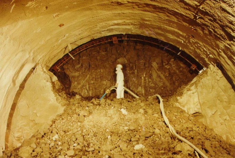
The Lehigh Tunnel No.2, part of a 4-lane motorway running East-West through Pennsylvania, was one of the first tunnels in the US built using NATM. Capacity problems of Lehigh Tunnel No.1 caused delays during peak times. The new tunnel was excavated using top heading, bench and invert excavation with shotcrete support. To achieve a completely dry tunnel a PVC membrane was installed between primary shotcrete lining and the final cast-in-place lining. Tunnel rehabilitation including the installation of a PVC membrane and thermal insulation in the air duct was performed to the original tunnel.

Activity
Design
Final cost
$25,000,000
Ventilation duct with ice build-up
Installation of waterproofing system
Typical Cross Section
View of exisiting Tunnel Portal
Preparing Tunnel Portal to start Excavation
Tunnel Face with Shot Holes ready to blast
Formwork for Cast-in-Place Final Lining
Final Lining and Invert Drain Trench
Lehigh Tunnel No. 2 - Completed Southbound Portal
Lehigh Tunnel No. 1 - before Rehabilitation
Frozen Water Leakage in Upper Air Duct
Drainage
Lehigh Portals Tunnel No. 1 (left) and the new Tunnel No. 2
Preparations
Spiles and anchor
Spiles and anchors
seeping water
Profile check
Carrier
Essembling the formwork
Incident doing form essembling
Glossy tunnel walls
Glossy tunneling
Finished tunnel
Reinforcement of roadway
Pipes
Northportal
Lehigh Tunnel #1 & #2 South Portal
Project number
115D
Final cost
$25 million USD

Washington Dulles Airport Pedestrian Walkback Tunnel

Service Performed
Final design including FEM structural calculations.
Commencement - Services
February 01, 1998
Completion - Services
December 01, 2001
Location
45045 Aviation Drive
Dulles, VA 20166-7528
United States
Technical data

Pedestrian Walkback tunnel, accommodating two moving and one central fixed walkways, 770 ft long, Section of 41 ft x 27 ft. A Mechanical Room with a 37 ft long x 32 ft. span . Tunnel passing 15 ft beneath the main airport taxiways.

Geology description

Residual soils, decomposed rock and siltstone bedrock.

Geology types
Description

An extensive underground people-mover train system and a fixed walkway tunnel between terminals are central to a multi-phased mega program of modernization and expansion for the Washington Dulles International Airport. The pedestrian walkback tunnel, a part of the expansion plan, crosses below two airport taxilanes and will connect the Main Terminal with Mid-Field Concourse B. The tunnel was designed as a multiple-drift NATM excavation, whereby cover beneath the taxilanes was less than a tunnel diameter at only 4.5 m. Excavation was therefore designed as a very controlled sequence with top heading excavation further divided into two side drifts.

Activity
Design
Categories
Final cost
$13,000,000
Construction methods
Max Overburden
Min:10 Max:20
Max Excavation Area (m2)
Min:1200 Max:1200
Tunnel length
Min:770 Max:770
Walkback tunnel cross section
Access shaft and portal under taxilane
The new tunnel in relation to the airport taxiways
Excavation of Access Shaft
View from Portal to Main Terminal Building
Excavation of Connector Shaft at Junction to Walkback Tunnel
Roadheader entering the Tunnel
Access Tunnel Walkback Tunnel Junction
Walkback Tunnel Shotcrete Canopy
Flexible Membrane Waterproofing System applied to Tunnel Invert
Installation of Waterproofing System in Connector Shaft
Fixing of Waterproofing Membrane
Completed Shotcrete Final Lining
Shotcrete canopy, girder erection
Shotcrete Arch - South
Hanging Steel Mesh
Hanging Steel Mesh
Hanging Steel Mesh
Girder completly installed
Shotcrete canopy completed
Project number
207D
Final cost
$13 million USD

Heathrow Express Rail Link

Service Performed
Tender design, detailed design and construction supervision.
Commencement - Services
April 01, 1990
Completion - Services
December 27, 1992
Location
Nelson Road
London
TW6 2GW
United Kingdom
Technical data

Railway link between Heathrow Airport and Paddington Station 2 underground stations: (Central Terminal and Terminal 4). Trial station tunnel with three different excavation and support sequences; lenght: 100 m, diameter: 8 m approx.

Geology description

Soft ground, terrace gravels overlying London Clay.

Geology types
Description

The Heathrow Express Link provides a 15 minute high speed rail service between Paddington Station and Heathrow Airport. A 7.25 km spur running for the most part in tunnel provides the airport with underground stations at the Central Terminal area (Terminals 1, 2 & 3) and Terminal 4. Provision was also made for a link to the at this point proposed Terminal 5. The 5.5 km long tunnelled section will pass under the M4 motorway with the portal located to the north.

Activity
Design
Final cost
$2,200,000
Removal of temporary side wall
Shotcrete lining completed
Finished adit
Subway entry at surface
Lattice girder and wire mesh installed at invert
Excavation of bench completed
Excavation of the side drift
Invert,installed lattice girder and wire mesh
Installed pressure cells
Installation of L.G. in top heading of side drift
Proposed Excavation Sequences
Instrumentation Scheme
Finite-Element Calculation
Excavation Sequence Type 1
Excavation Sequence Type 2
Excavation Sequence Type 3
Completed Trial Tunnel
Finished Platform Heathrow Central Terminal
Concourse Tunnel
Completed Escalator Shaft
Project number
172D
Final cost
£2.2 million GBP

Pages